|
|
Post by scanrail on Jul 25, 2022 10:17:42 GMT -5
Hi friends, I prepared Installation Manual for SW1500 series digital decoder. It can be downloaded here (PDF): ZDL-AZL-SW.pdf (809.91 KB) Each decoder will be also supplied with printed version of it. Greetings, Alex |
|
|
|
Post by scanrail on Jul 13, 2022 9:36:06 GMT -5
Hi friends, First of all, I would like to share excellent news – this project is not dead  But this is not even the most important thing. I would like to say that first series copy of this decoder in its final version is ready. Here is it, top side: 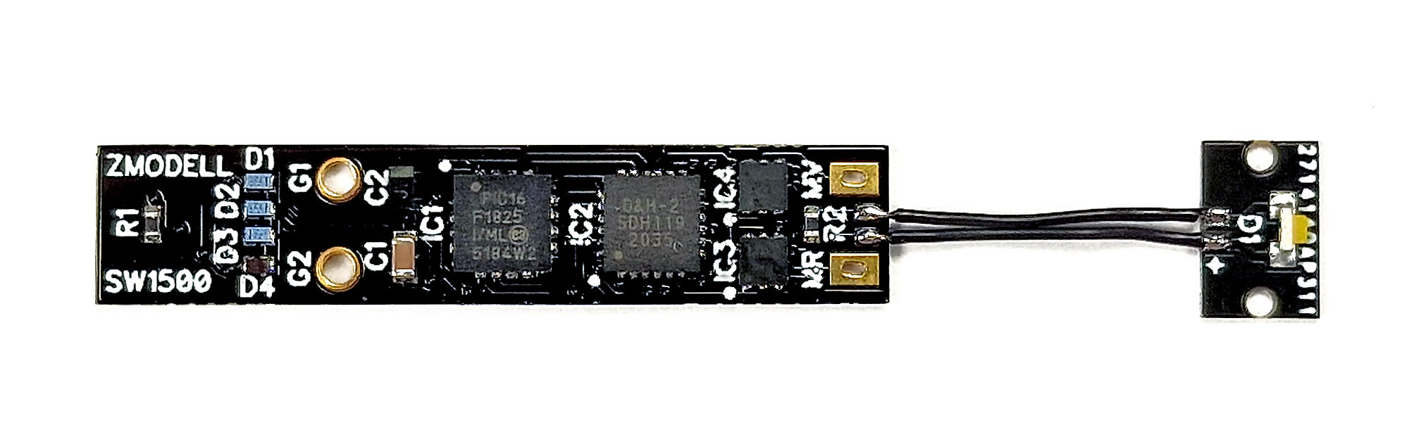 Bottom side: 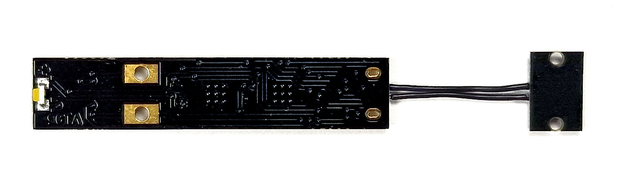 In the final version, I used different material – high grade FR4 with increased strength, because I required a very low thickness – only 0.25 mm. I also used black mask and gold coating. The last one was used to increase reliability of mechanical contacts between chassis (two separate parts of which transfer a power to the decoder), pads on the circuit board and output pins of the motor. Circuit boards were ordered back in Ukraine before the war in the beginning of the last winter. Recently I had a luck to receive them safely here in Germany, including all required electronic components. The quality is simply excellent: 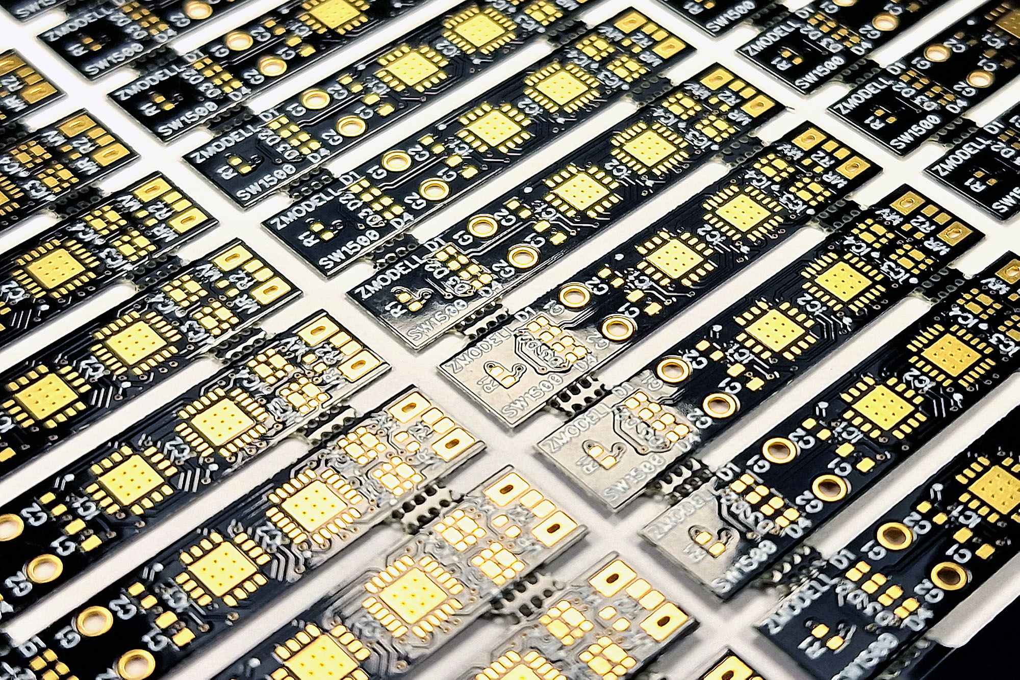 In the final version of circuit boards, I changed the shape and size of pads and holes for connecting the motor output pins – now they provide more reliable electric contact and are better secured from the short circuit with the chassis. I also found a very good supplier of wires and cables here in Germany – I found an excellent 21-strand wires with only 0.5 mm outer diameter (including insulation) there (normally, such thin wires have only 7 strands). I used this kind of wires for connecting two circuit boards of this decoder. As you can see, thanks to the smallest possible components and very low thickness of the circuit board, we got a very thin decoder – only 1.16 mm thick: 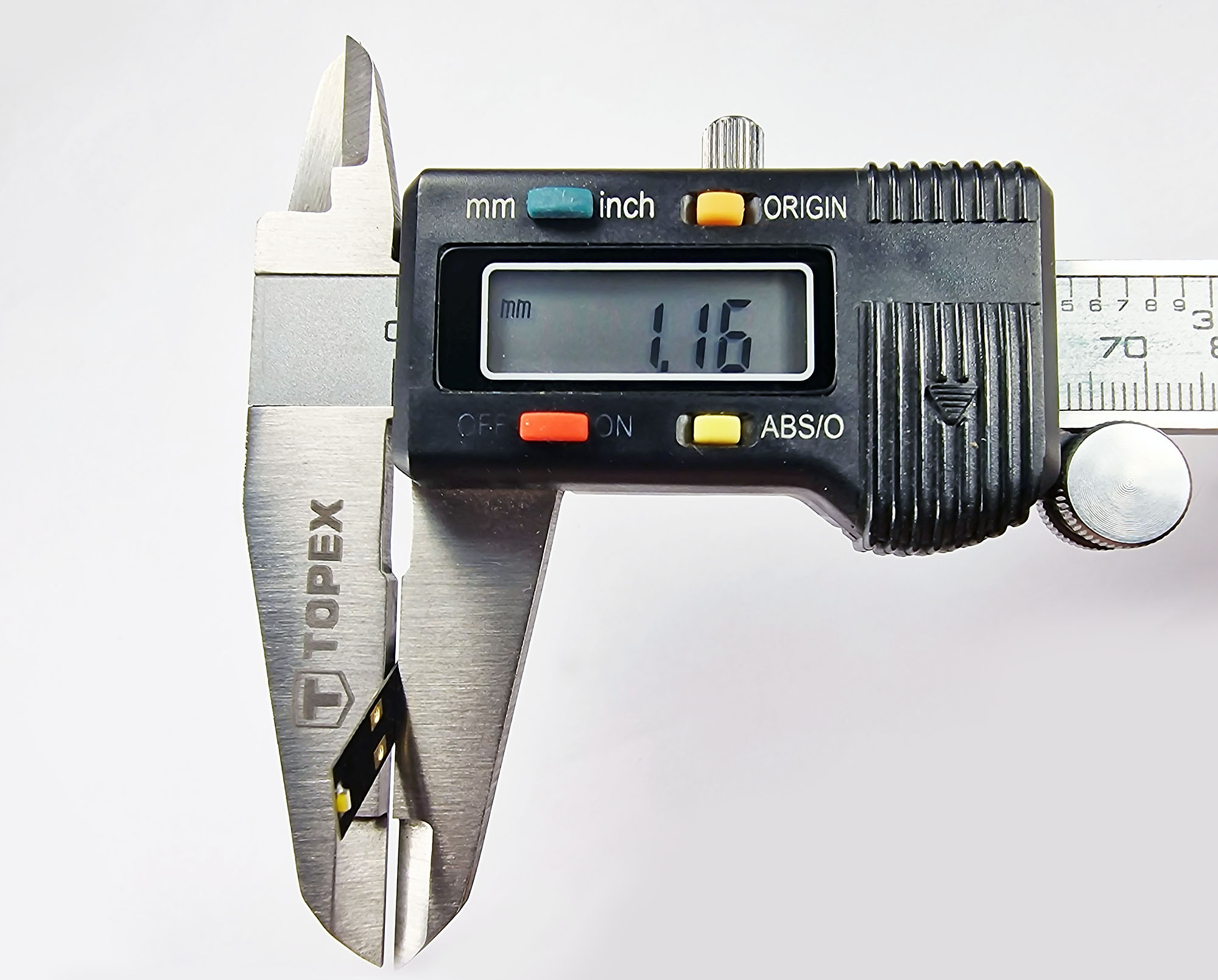 One more time regarding disassembly of this tiny locomotive: I recommend following recommendations posted here on the forum: azlforum.com/thread/2046/emd-sw1500-removalIn general, I did the same: I carefully removed halves of the fuel tank, and then slowly, with very small steps pulled out the chassis outside of the housing of my Union Pacific SW1500 locomotive. The only difference is that I used a flat screwdriver of my Swiss knife. All surfaces of these knives are very well polished, and all edges are rounded, so there is no risk to damage the locomotive (of course, if everything is done carefully enough):  Here you can see a disassembled locomotive. I also left an original analog circuit board on the picture for comparison: 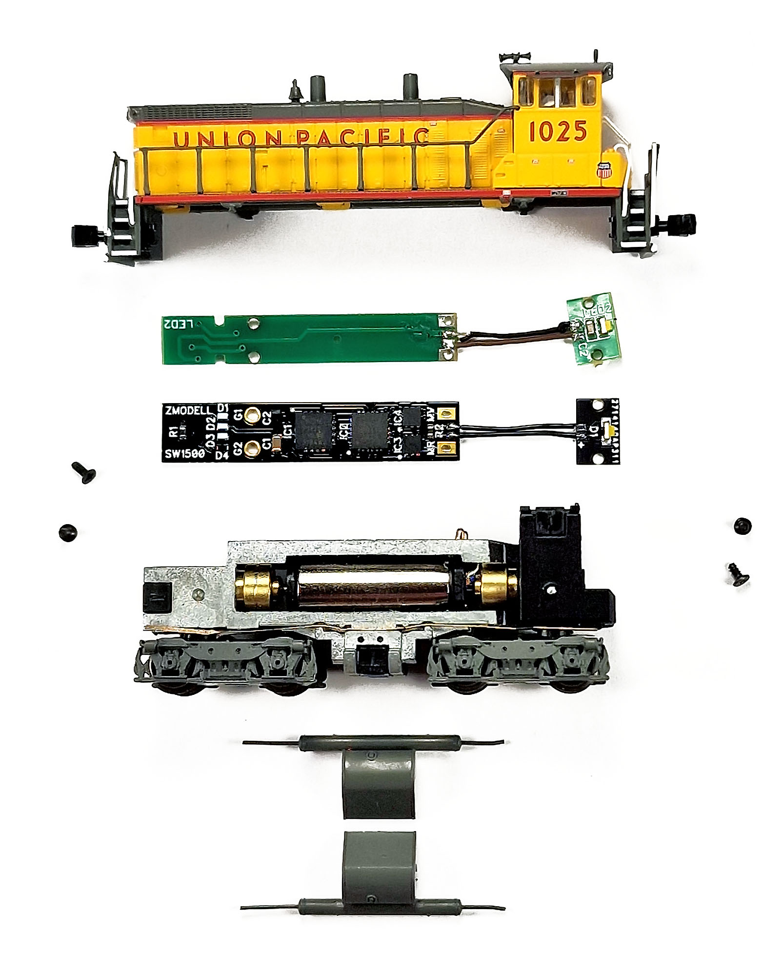 One important point to consider before installing the decoder: it may be necessary to adjust pins of the motor outputs. If you believe that electric contact between the pins and the holes in the circuit board is not reliable enough, you may do some fine adjustments to the pins, as shown on the following picture – slightly pull them apart and then bend them a little towards the cabin. Once again: normally it does not needed to do this; perform this only if you believe that it is really needed: 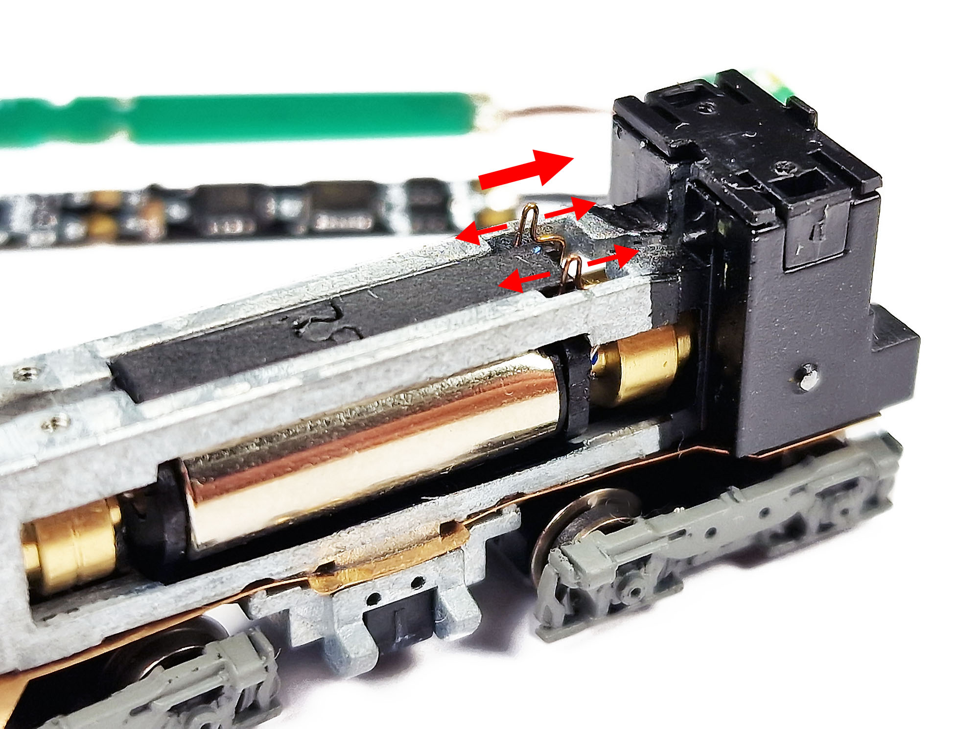 Now it is time to install the decoder onto the chassis. Another important point: it is necessary not to overtighten the screws that hold the main circuit board. Stock screws have reverse conical heads, so it is quite easy to bend a thin circuit board in case of overtightening. After fixing everything in place, wires that connect small circuit board with LED should be carefully threaded inside the gap between halves of the chassis. While doing this, make sure that these cables don’t touch the driveshaft of the motor: 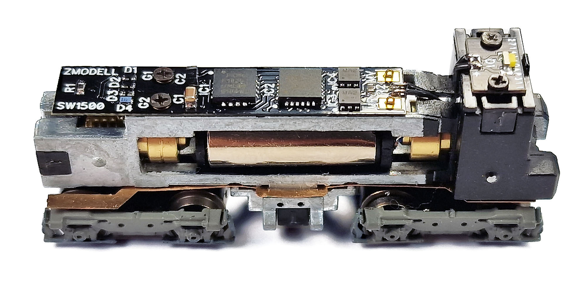 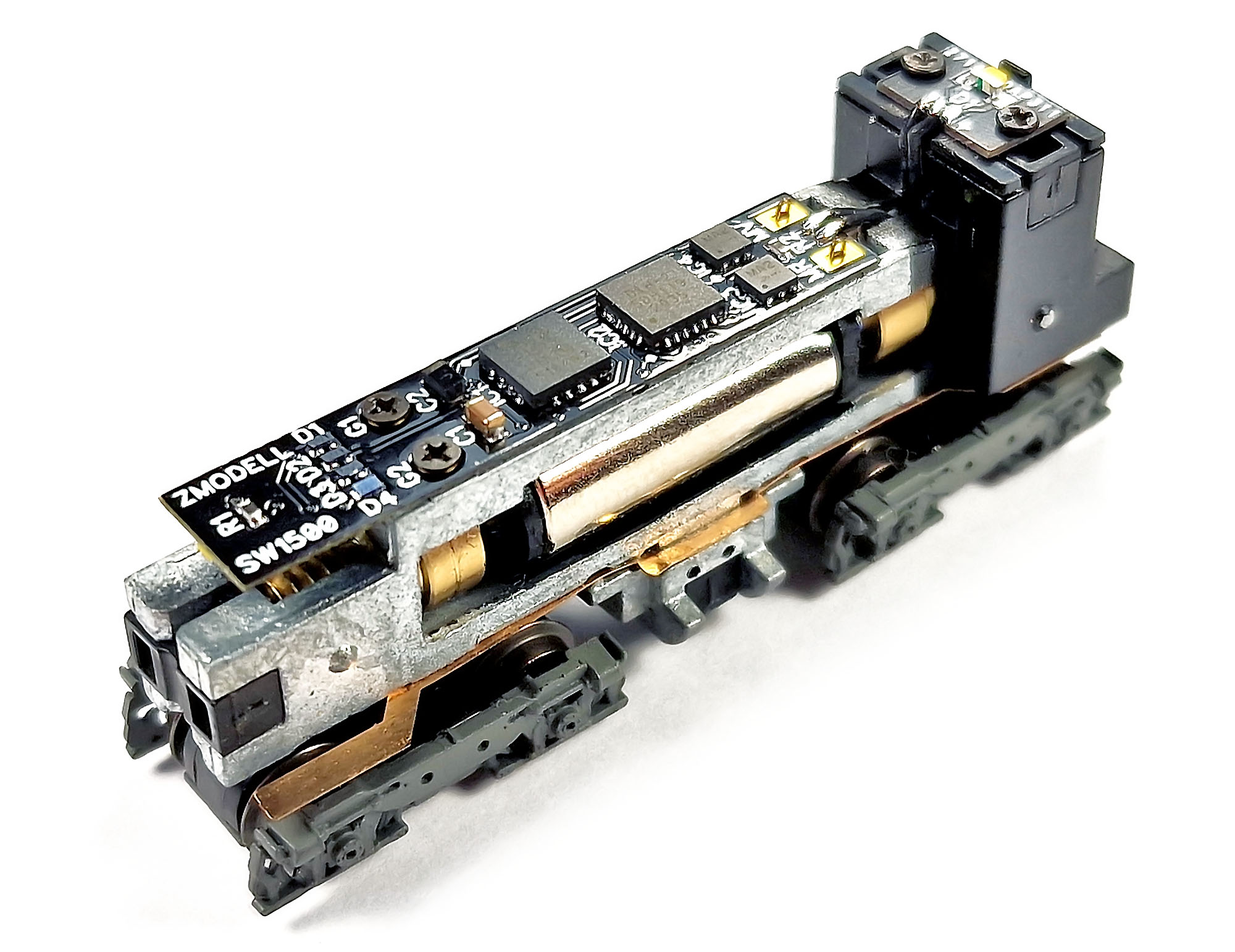 On this picture, you can see how thin this decoder indeed is: 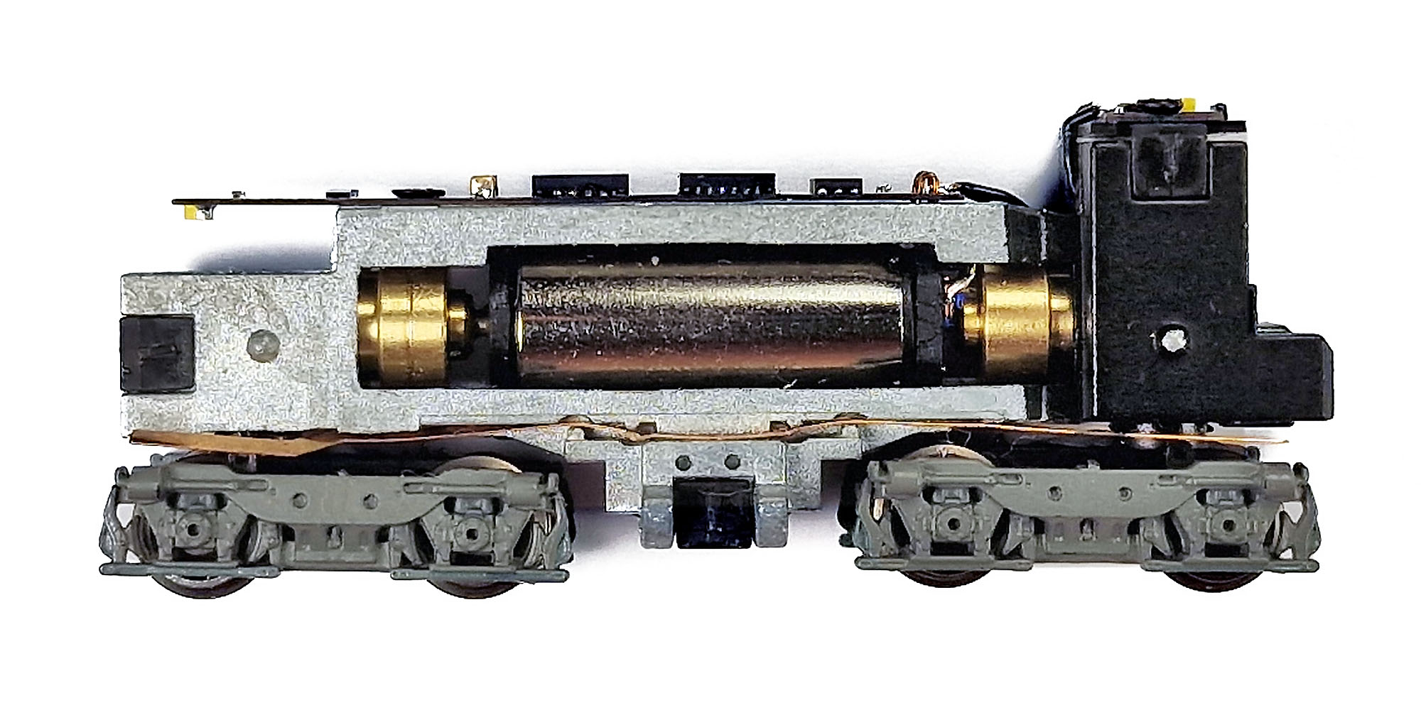 But don’t worry – the circuit board is made from a very good material, it does not feel like a “piece of paper”, it is rigid enough. I would like not to leave without attention one more point: despite I did my best to design the motor connectors on the circuit board in the safest possible way that leaves almost no chance for the short circuit with chassis, the construction of the chassis, in my opinion, is a little bit “risky” at this point. Thus, I recommend to examine connection between the digital decoder and motor very closely, and even test it for short circuit with chassis using a multimeter if needed. After installing the decoder, I put the chassis onto the small test circle in order to check if everything works correctly before installing the locomotive shell: 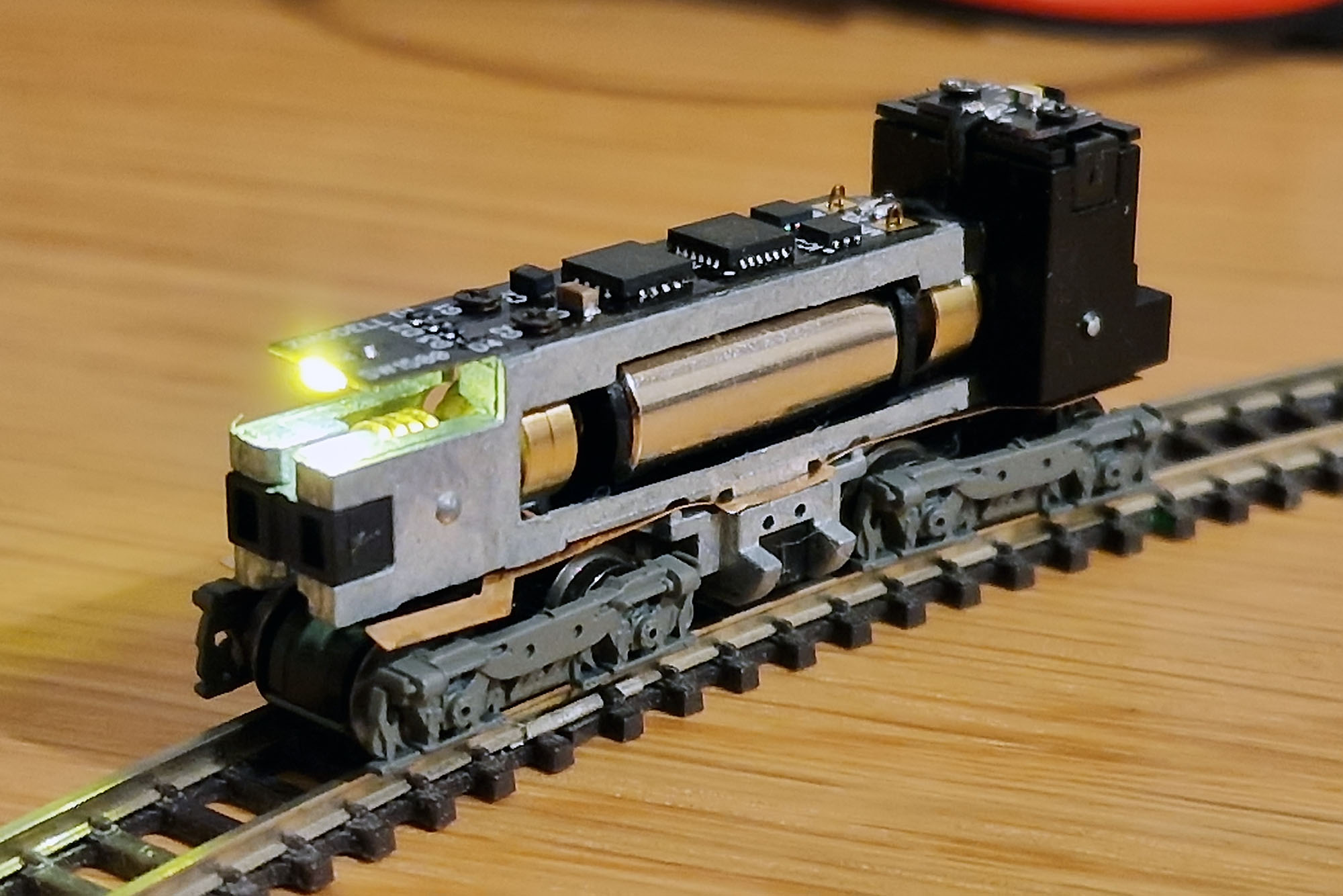 I was so lucky when it turned out that everything works flawlessly with decoder’s default settings. Maybe the only thing you need to do is to adjust CV5 (max speed) to the maximal value 127 (it is 92 by default), as this locomotive runs already quite slowly in analog mode. Now we will get an answer to the most important question that was my deepest concern – will the decoder appear to be thin enough to fit inside such a tiny model without any problems? Of course, all preliminary measurements and calculations always precede any development and production, but in many cases, only the practical tests can prove if design was correct. So, just look at these pictures – they speak for themselves. No gaps between the chassis and the housing at all! The locomotive looks exactly the same – both before and after installation of the digital decoder. I am proud that this development is indeed successful in all terms: 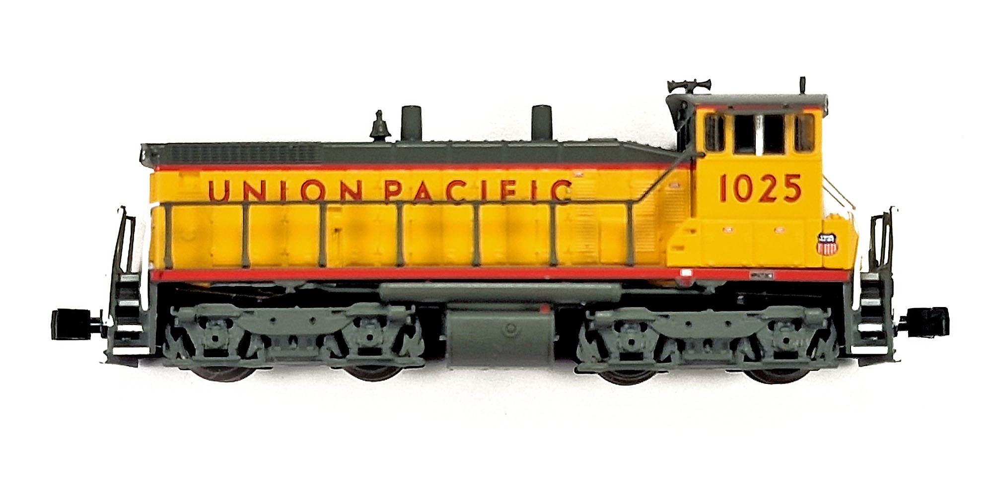 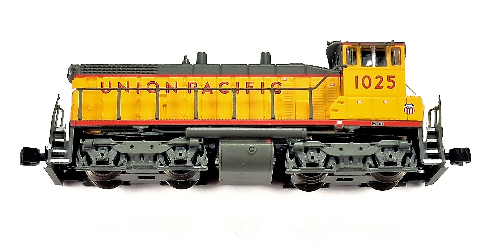 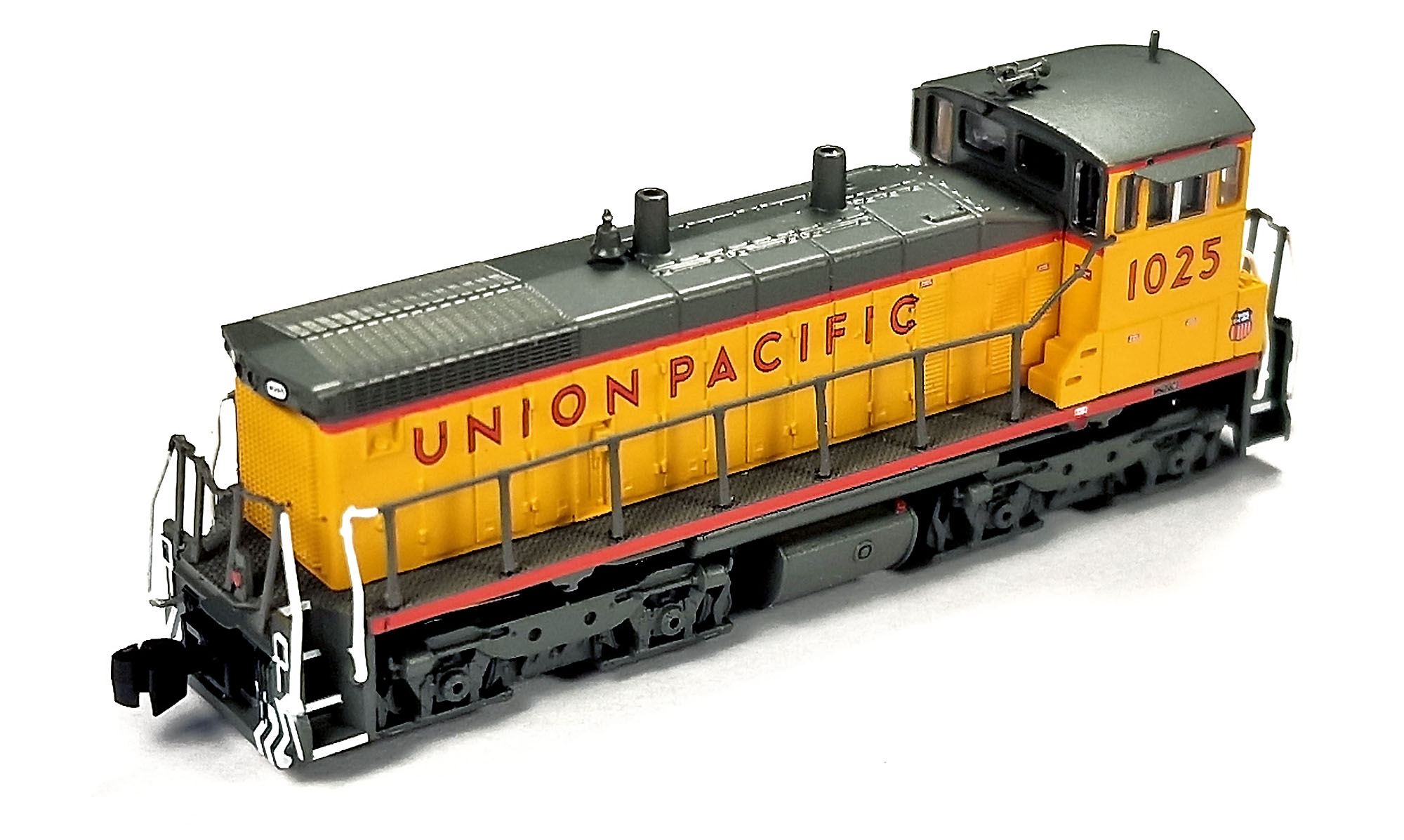 For running trains in digital, I use Märklin CS3 Plus with digital signal reducer from Arnold Hübsch (AMW). Here is a short video where you can see a newly digitized AZL SW1500 Union Pacific running on the small test loop: Here are some funny (and not too funny at the same time) facts regarding assembly. I was ready to place an order at the local PCB assembly factory back in Ukraine this winter shortly before the war. But all of you already know what happened later. The first series copy of this decoder I assembled manually yesterday here in Germany – on the kitchen table, using minimal amount of required equipment that I was lucky to get from Ukraine thanks to my friends who stayed there in Kiev: 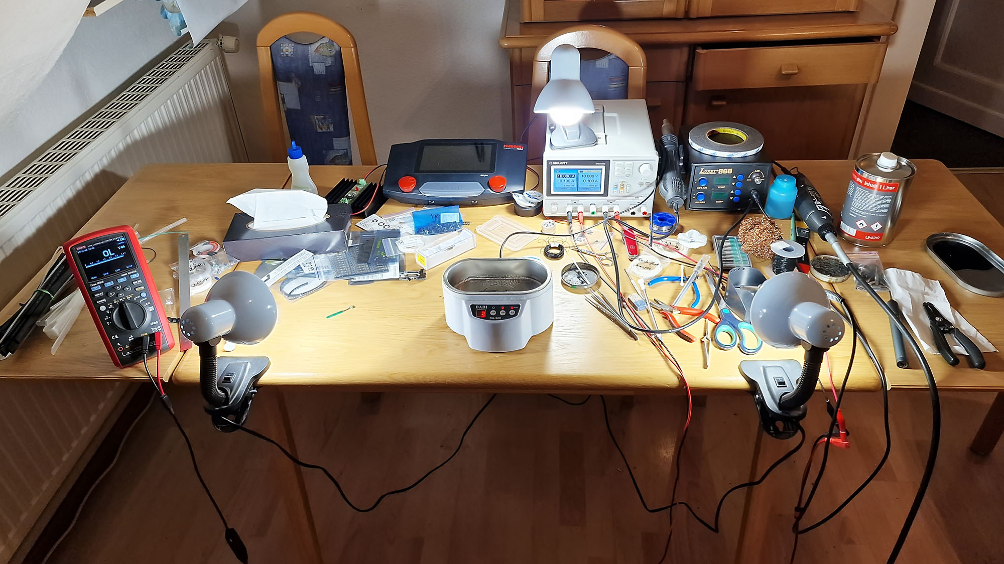 Here is one of the production stages: applying a special SMD soldering paste onto the circuit board using brass photo-etched stencil before populating electronic components: 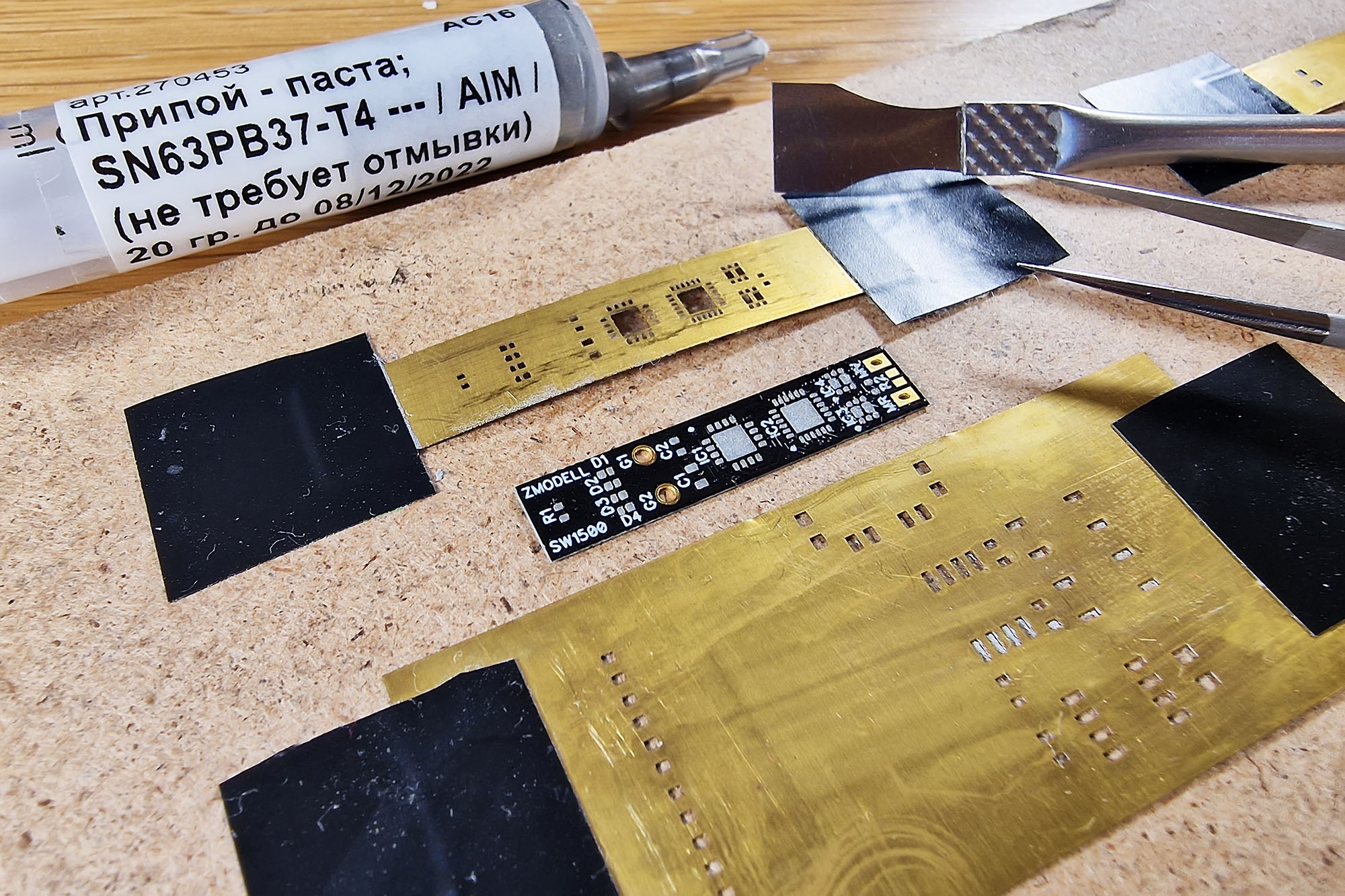 Since it is impossible for me to produce all ordered decoders at home (the quantity of orders I received is too big for home production), I am going to find a solution for this here in Germany. But the only thing I would like to ensure everyone about – is that I will do my best to finish this project in any case. And for sure, I will keep everyone informed regarding any updates on this subject. Best regards, Alex |
|
|
|
Post by scanrail on Feb 7, 2022 15:30:08 GMT -5
|
|
|
|
Post by scanrail on Feb 4, 2022 5:47:09 GMT -5
I wish I had 4 hands and 48 hours in a day, but I doubt it is possible Regarding GG1 locomotives: their availability depends on current offers of Märklin donor models on the aftermarket. I noticed that Märklin GG1's are constantly disappearing with years, and remaining ones are being offered for higher and higher prices. Thus, producing them in sellable quantities seems to me somewhat problematic too... |
|
|
|
Post by scanrail on Feb 3, 2022 19:13:42 GMT -5
Unfortunately, no one at the moment. This wind turbine is extremely difficult in production. Making each copy is a very time-consuming process, so I simply have not enough time to produce them in quantities sufficient for distribution...
|
|
|
|
Post by scanrail on Feb 3, 2022 14:38:45 GMT -5
Solar Panels
I would like to introduce my next development in the Power Series (models of items related to production and transmission of electric power; my first model was a wind turbine: azlforum.com/thread/1962/zmodell-power-series-wind-turbine) – solar panels. After some research, it became obvious to me that nothing similar exists in Z scale, and I decided to fill this gap on my own. I started from industrial type panels for building solar farms. Roof-type panels will come later. I refused to use any kind of plastic for this purpose – 3D printed either CNC milled, as assembled structure would be too brittle, and decided to use thick photo etched metal – 0.3 mm nickel silver. At solar farms, photovoltaic panels arranged in blocks in many different ways. I chose 5 x 2 variant as, in my opinion, the most optimal in terms of size and overall look on Z scale layouts. Solar panels come in 3-piece sets and feature half-etched elements. They are airbrushed with semi-gloss silver lacquer on both sides. I decided to use UV-printing technology to simulate photovoltaic cells – I printed them directly onto the metal surface on Mimaki UV printer. Combination of semi-transparent UV inks and silver base layer delivers a very good visual effect common to most metallic surfaces – variable reflectivity, depending on viewing angle:  What is important, solar panels can be assembled manually, without a help of any tools and with only one small drop of CA glue. I included detailed assembly instructions in the package. Finished panels look like this: 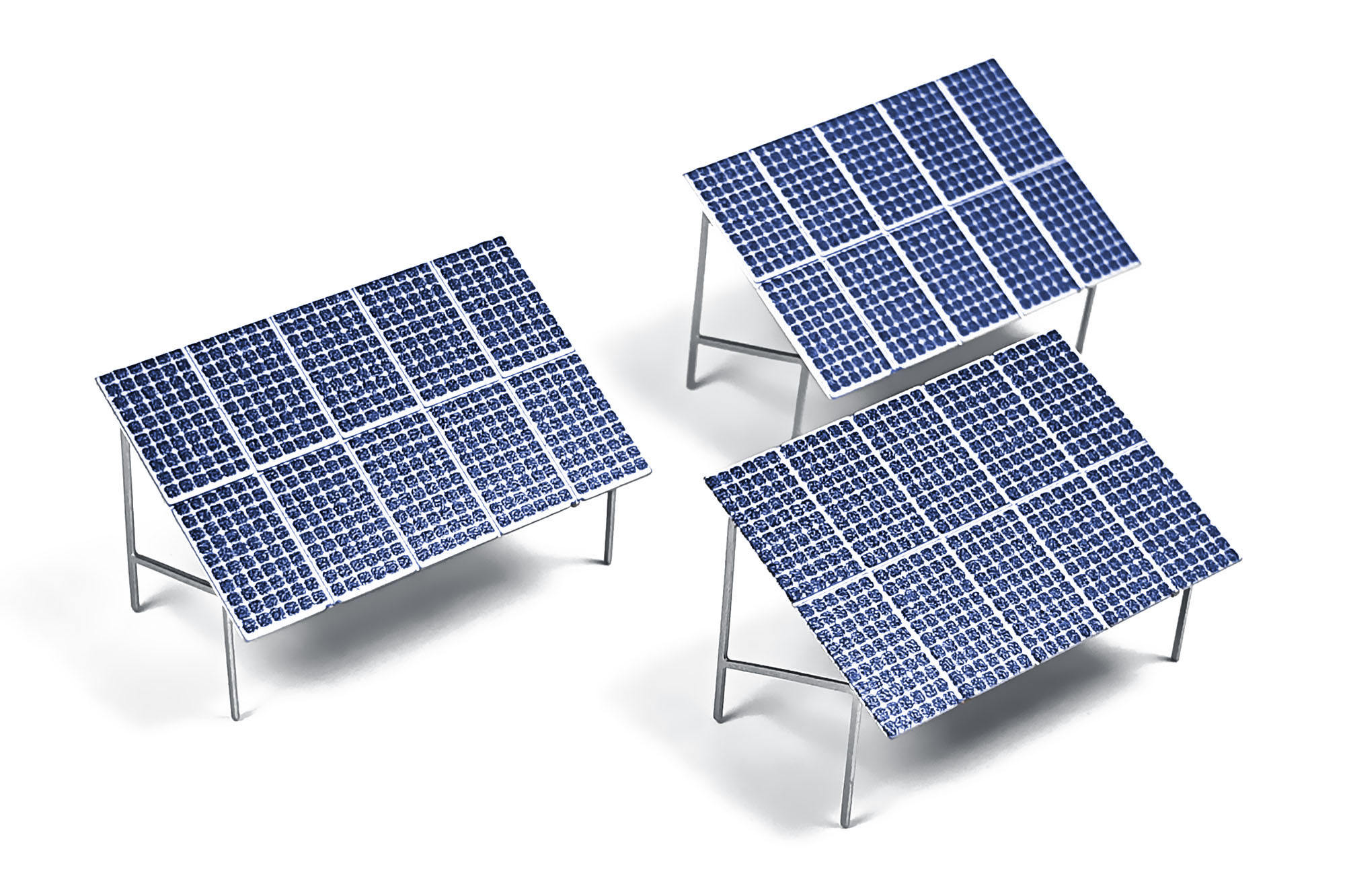 Solar panels should be installed to a depth of 5 mm in the surface of the layout. For easy installation, 5 x 2 paper drilling template supplied with each set. Bigger printable drilling template (12 x 8) is available for downloading here: Zmodell_ZM-MS-019_Template.pdf (54.84 KB) I made a small diorama with a nice rural backdrop to show how these solar panels can look on the real layout:  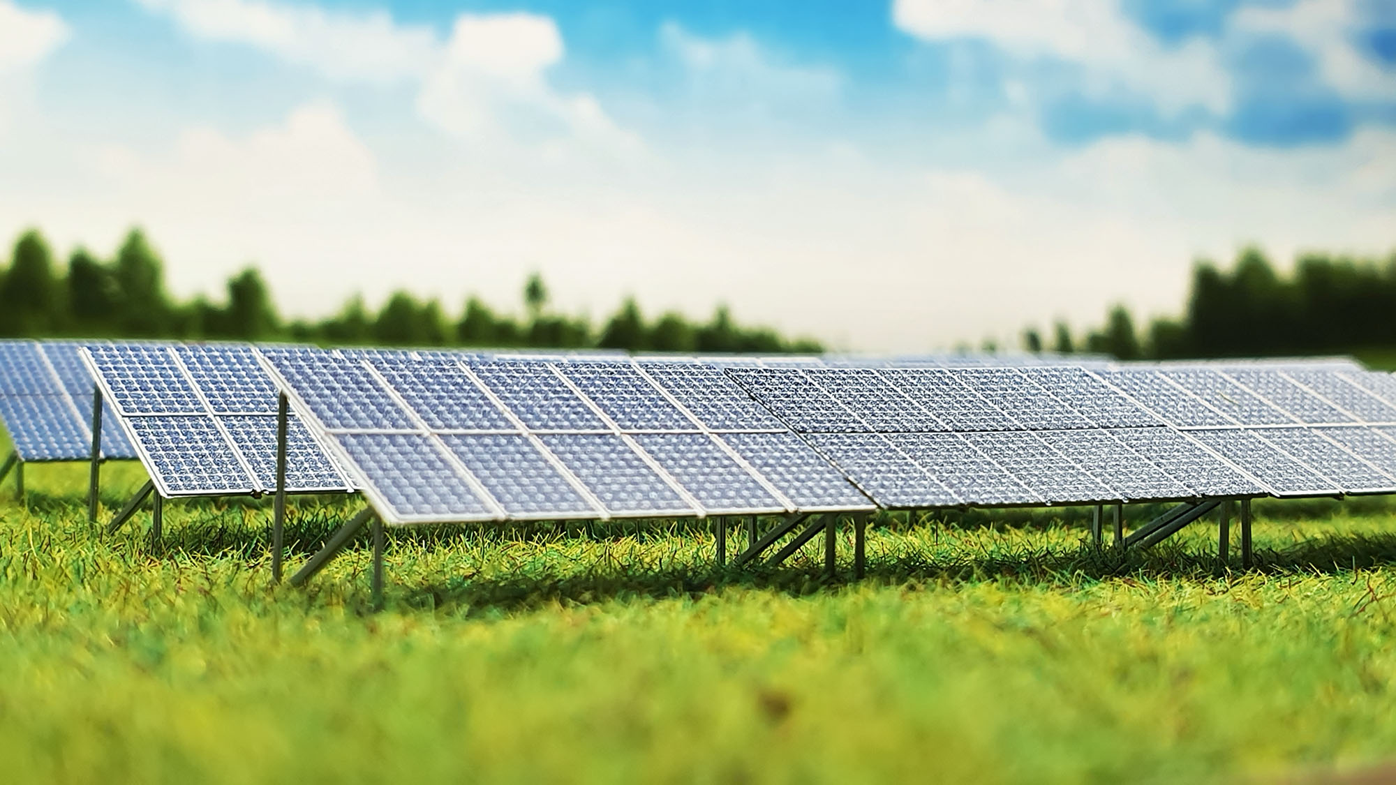 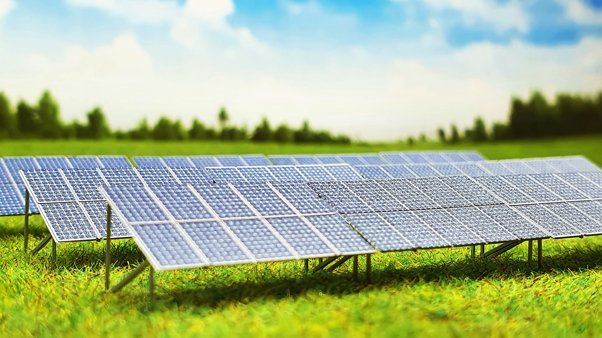 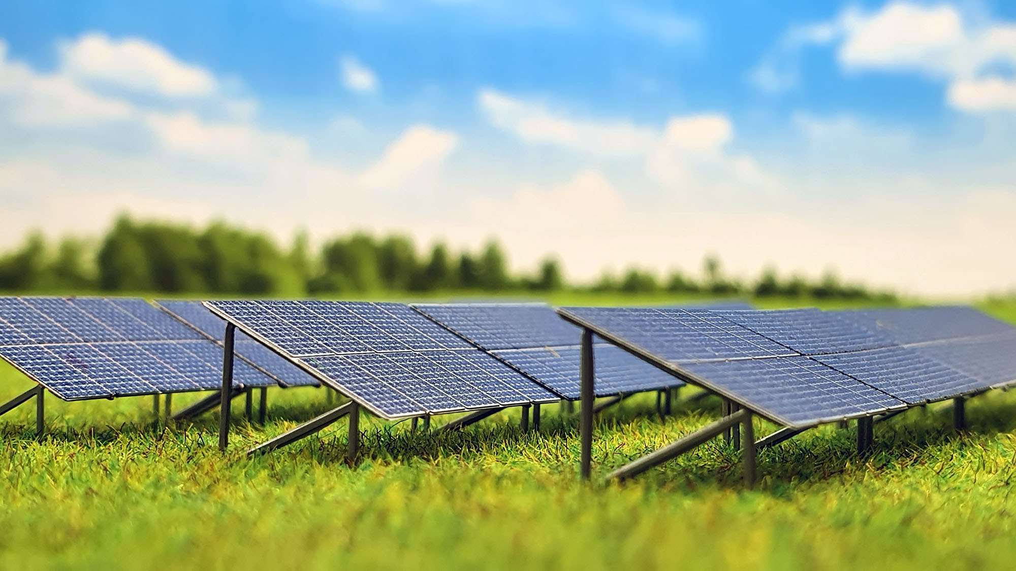   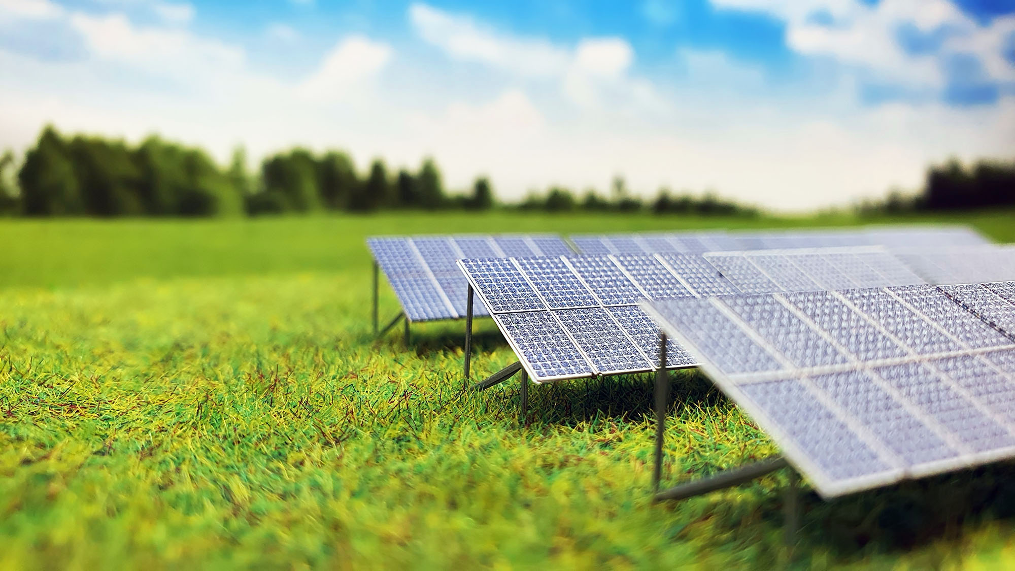 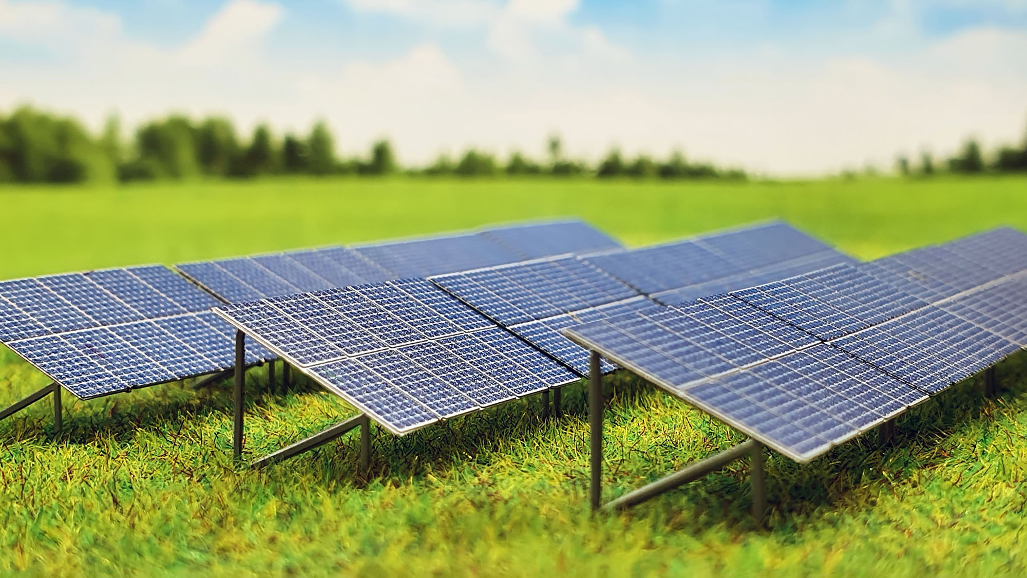 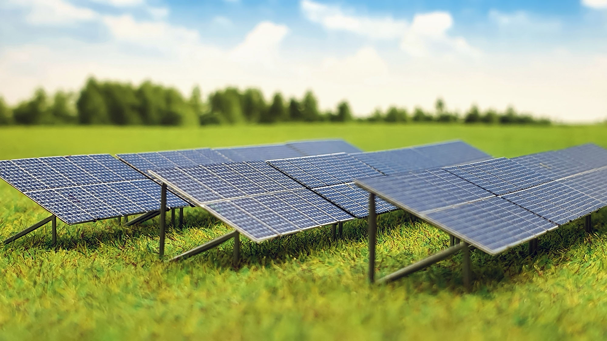  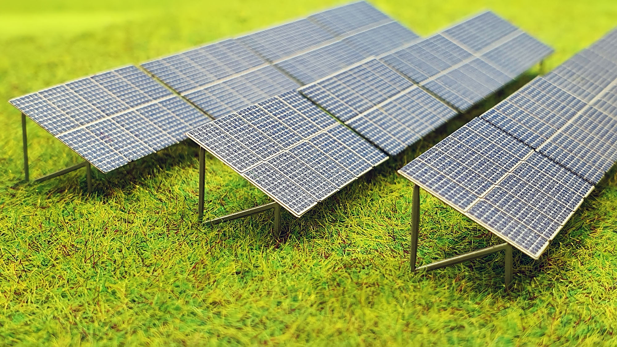 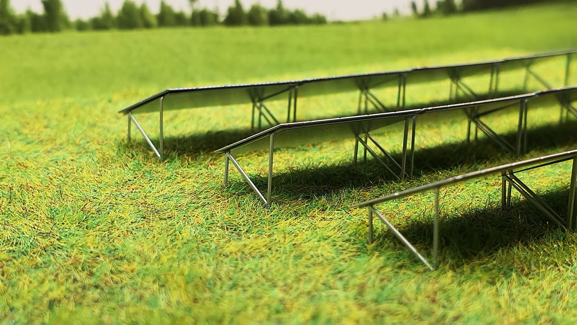  For reference, here are some pictures of real-life prototypes:   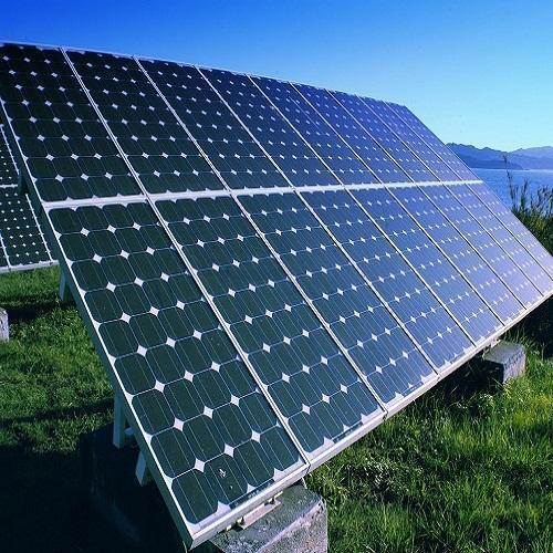   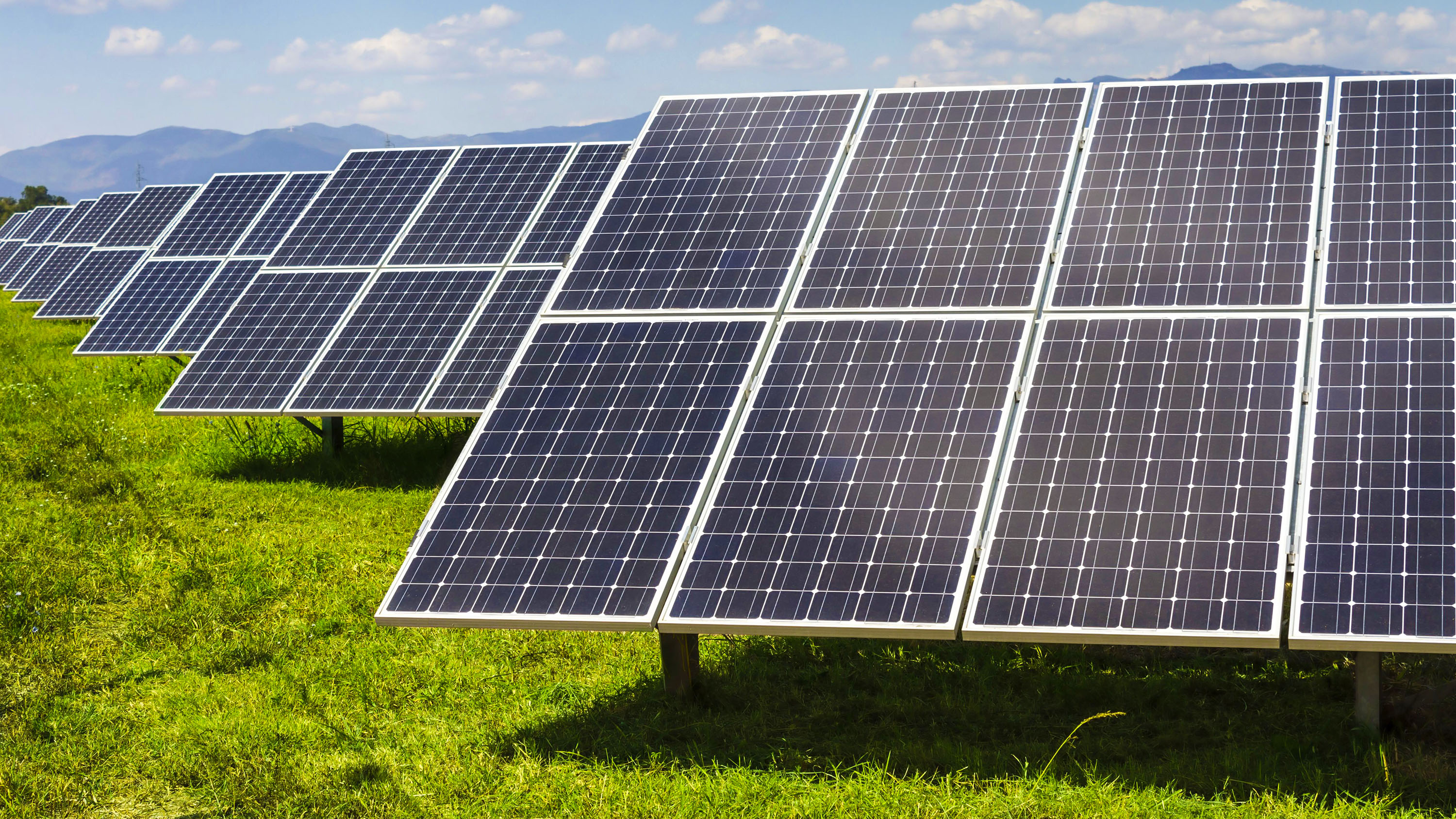 Solar panels are available here: www.zscalemonster.com/zmodell/Best regards, Alex
|
|
|
|
Post by scanrail on Feb 3, 2022 13:44:07 GMT -5
Hi friends, I continue adding new products and making them already available for sale in the USA. Here are these novelties. Manhole coversFirst, here is a small but beautiful accessory for layouts containing urban infrastructure – old style manhole covers with ornaments in two different variants. They are made of 0.1 mm photo etched nickel silver and airbrushed with “Dark Iron” metallic lacquer paint which simulates real color of cast iron manhole covers slightly polished by pedestrian either automotive traffic, for example, like on this picture: 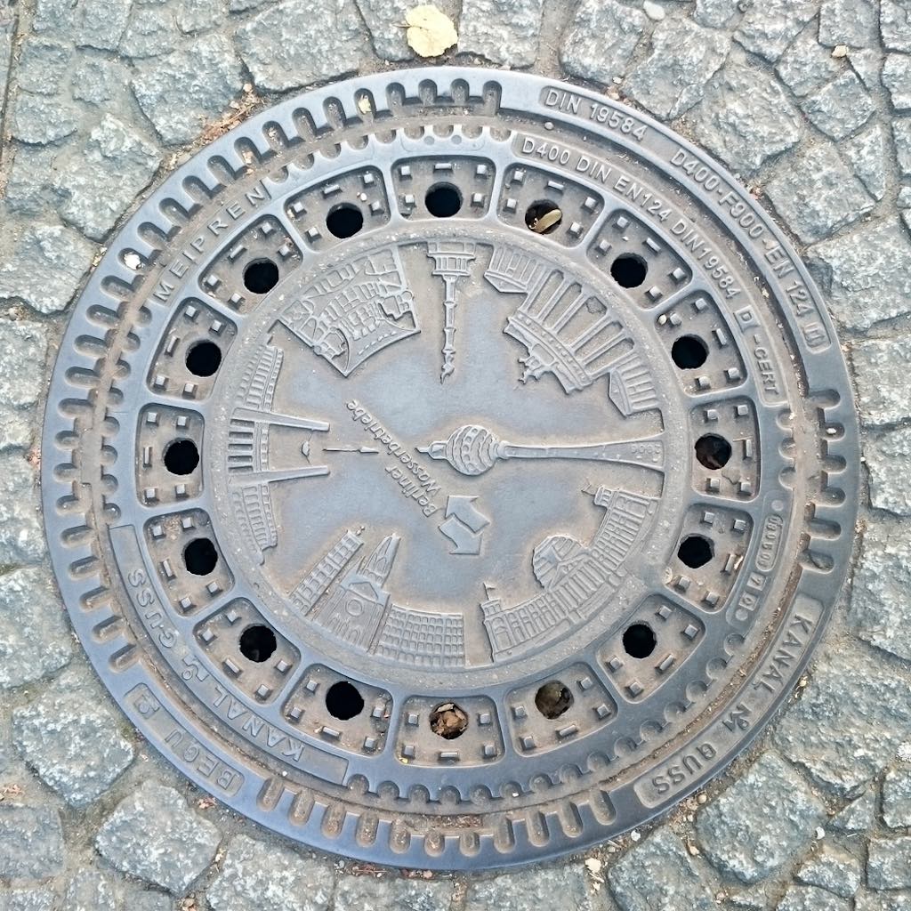 The choice of such a thickness of the material is due to the following reason: any thicker material will make ornament visibility slightly better; however, manhole cover will look less natural, as it will protrude more noticeably above the surface. Thus, I deemed 0.1 mm as an optimal thickness for this purpose. I prepared two variants – round with 4 mm diameter and square, 4.5 x 4.5 mm size. Both variants come in 10-piece sets:   Covers feature real through holes, just like in real prototypes: 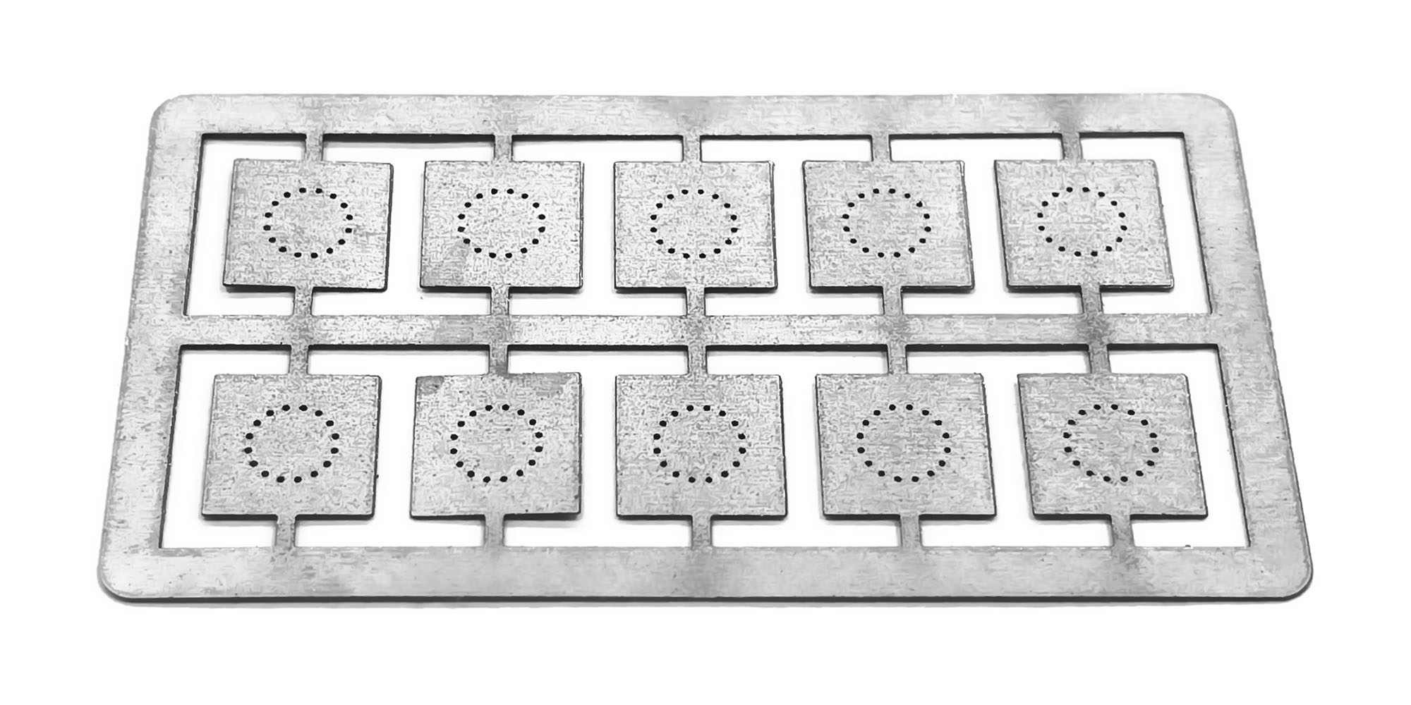  Prior to creating design of these covers, I reviewed many pictures of real prototypes; I was inspired mostly by variants common to Germany and which have, in my opinion, the most attractive and distinguishing look:  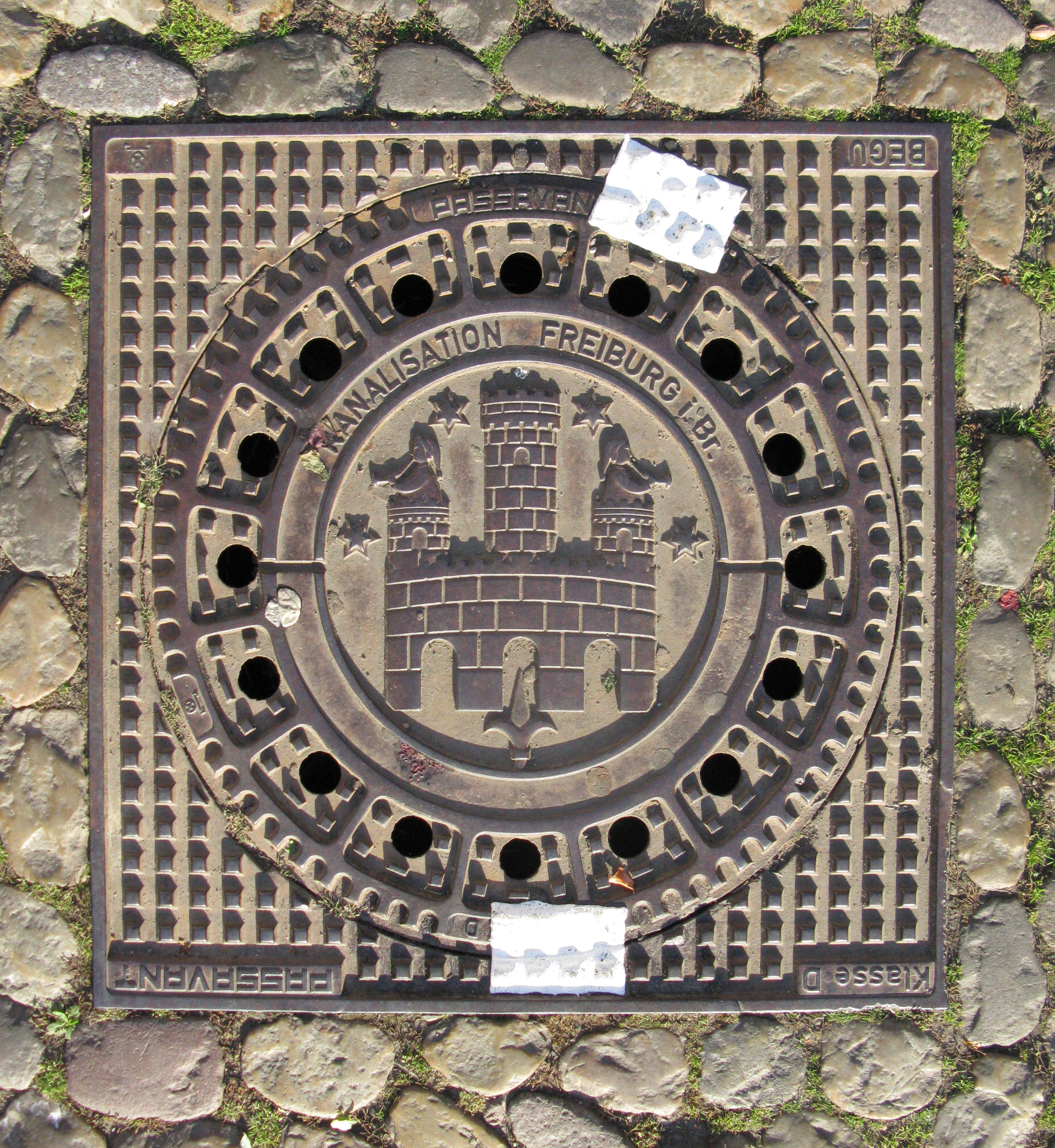 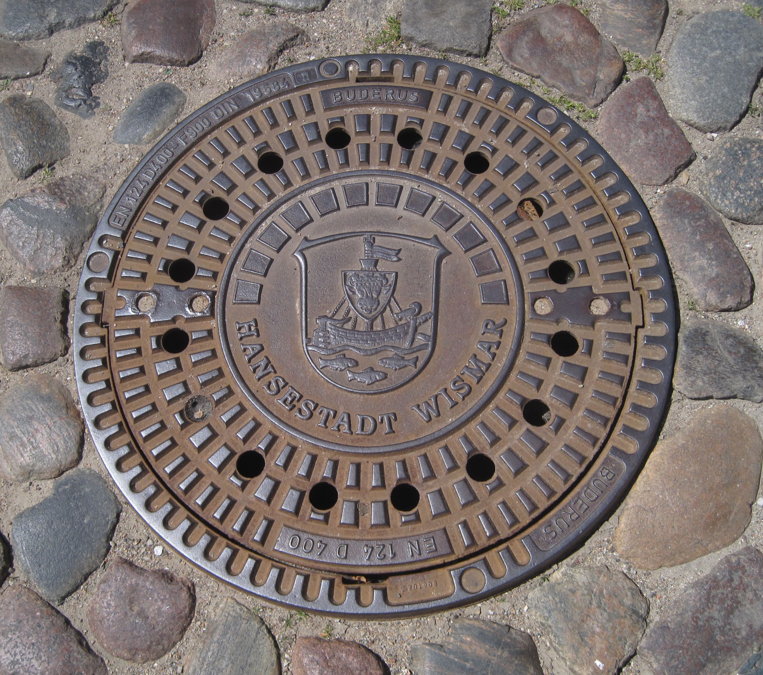 Of course, I had to simplify my design in order to adopt it to the technological limits of photo etching process in Z scale. For those who are interested in the subject, here is a small collection of manhole covers from different countries: commons.wikimedia.org/wiki/Manhole_coverHere are some usage samples: 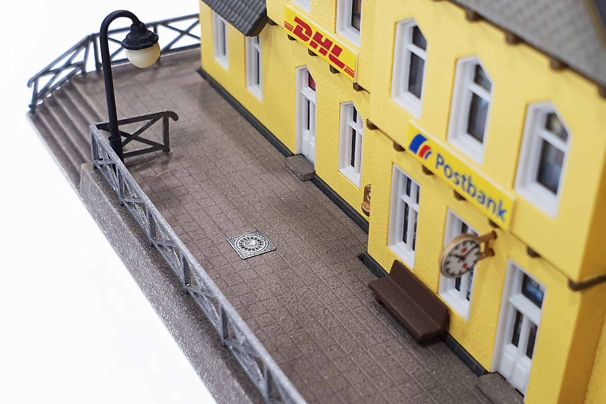 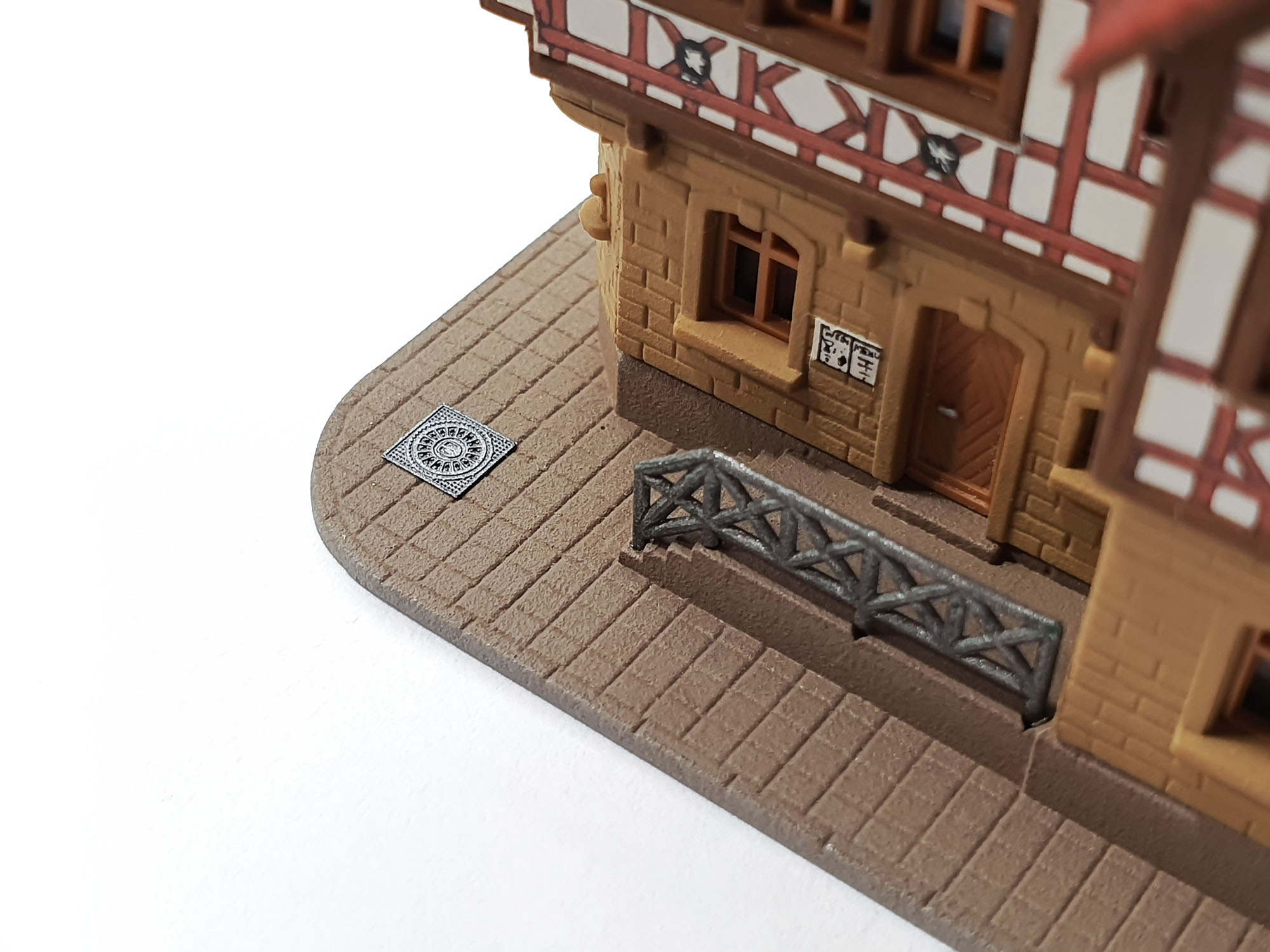 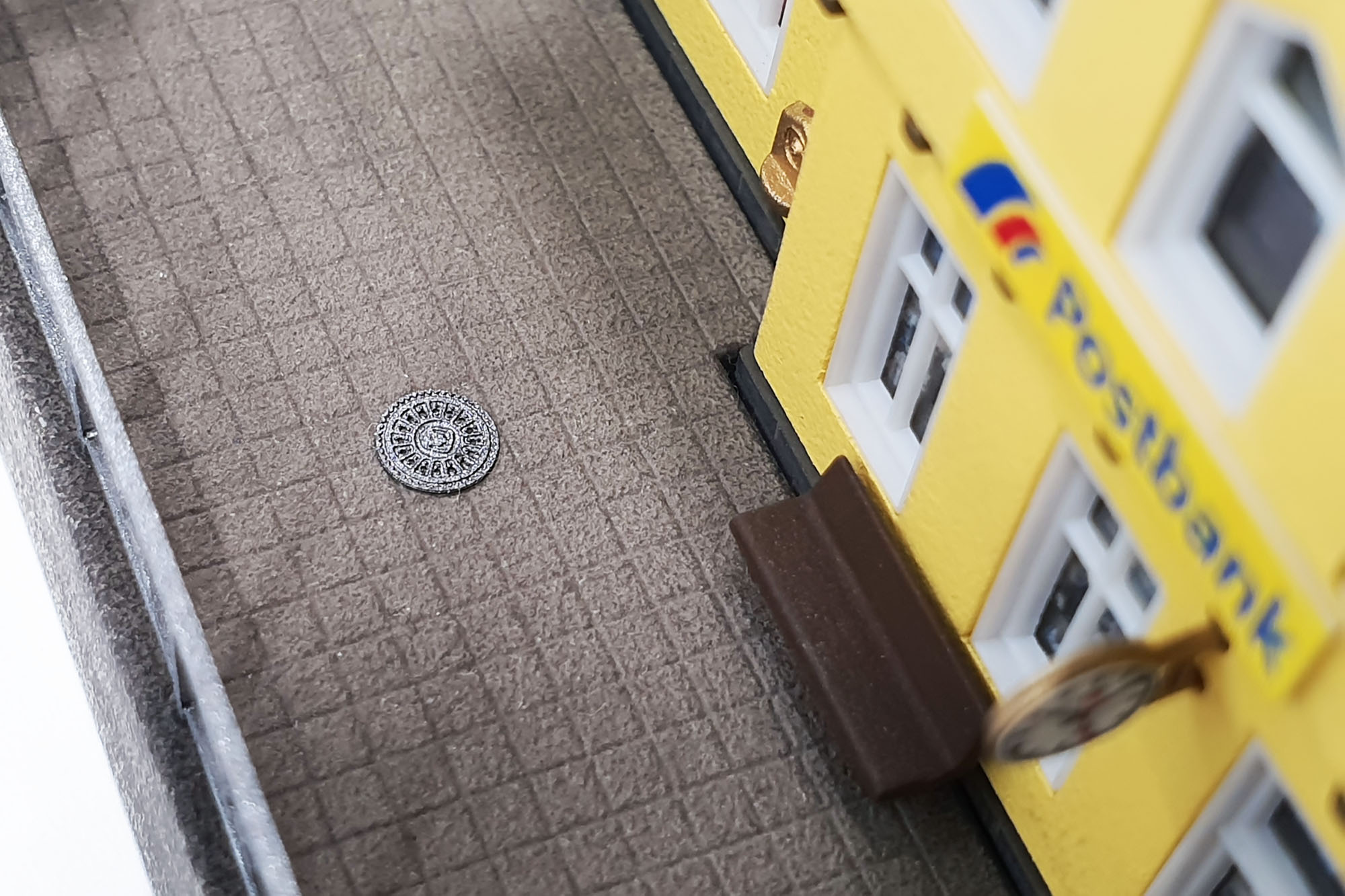 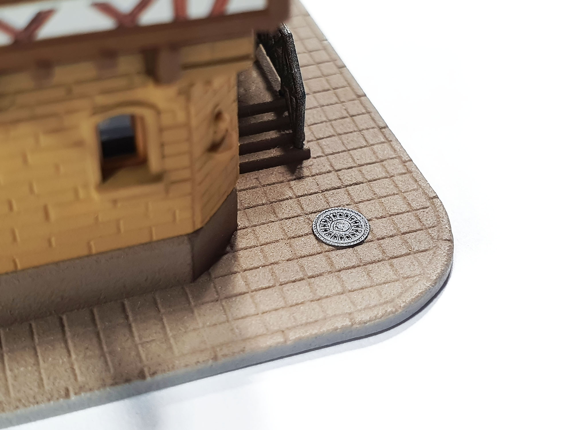 For fixing these tiny parts on layouts, I recommend using non-destructive glue, for example, Faller Expert Lasercut (Art. No. 170494). It is strong enough to fix small objects in place, do not cause any damage to the plastic parts and provides enough time for repositioning. Plastic glue may damage many types of materials, as well as painted surfaces (including airbrushed paint player on these manhole covers) and may not be strong enough for metal. Cyanoacrylate (CA) glue damages any kinds of surfaces in most cases, and almost does not allow repositioning. Both types of manhole covers available here: www.zscalemonster.com/zmodell/Best regards, Alex |
|
|
|
Post by scanrail on Jan 30, 2022 18:26:03 GMT -5
Hi Mark,
I am very grateful to you and all other friends and colleagues here for your concern and kind support! Luckily, I am OK! Unfortunately, no one can predict how far all the things will go, but we hope this dangerous game won't lead to something serious... But I believe one thing is obvious to everyone: it is impossible to calm down while a monkey is running around in the yard with a grenade...
Best regards,
Alex
|
|
|
|
Post by scanrail on Dec 13, 2021 15:52:20 GMT -5
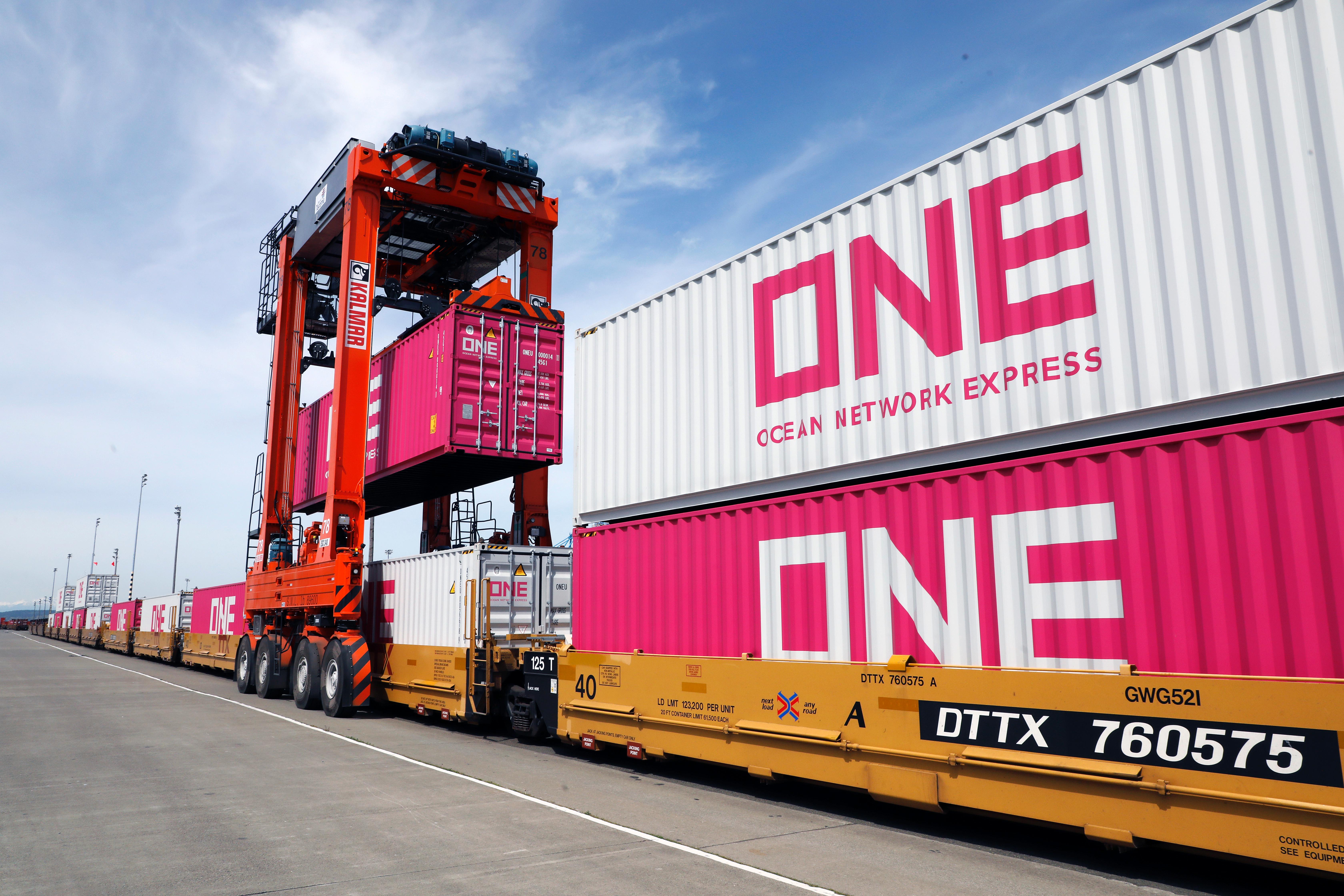
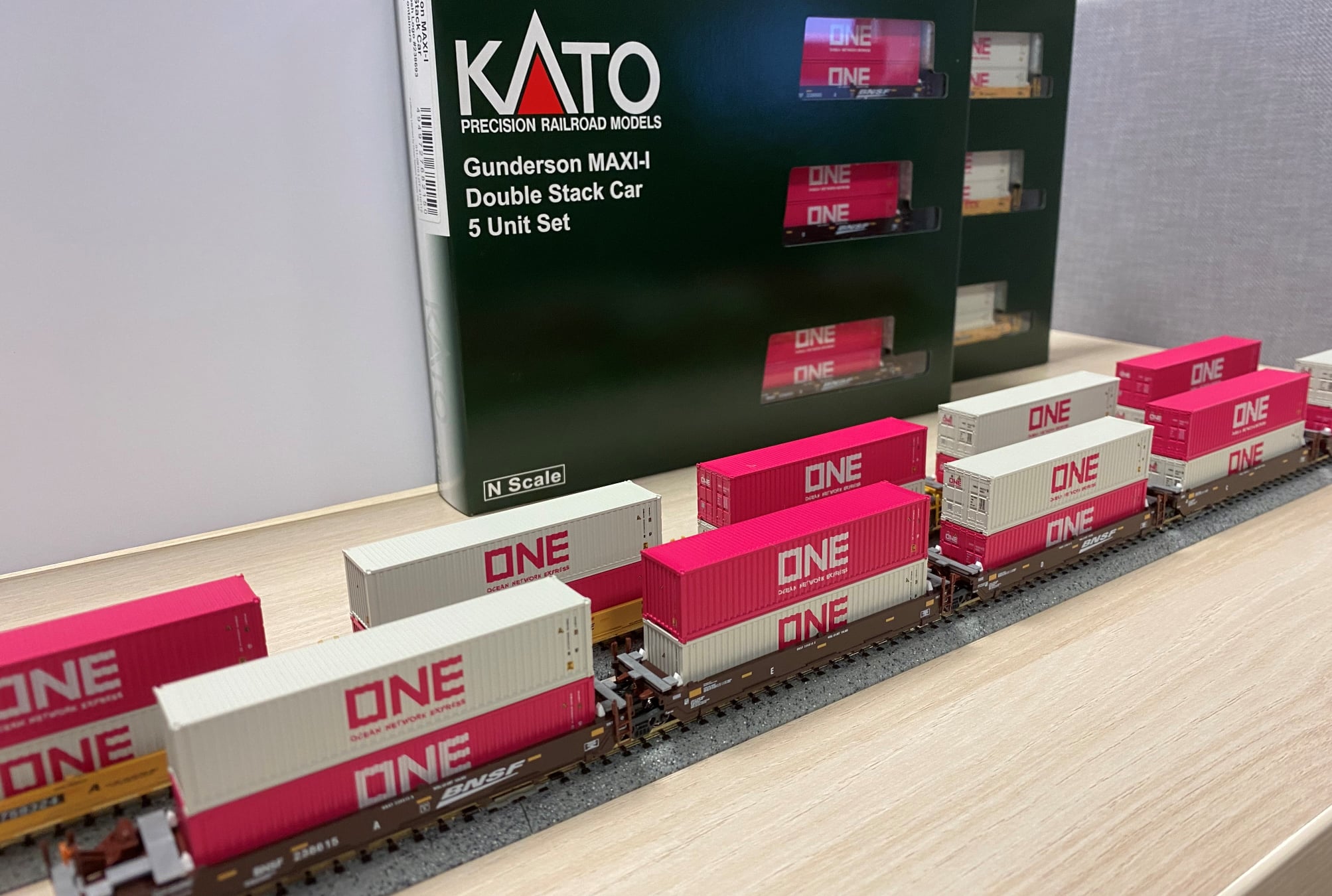
Alex: ...choose only one! Surely, only one one - ONE  However, in pair - pink and white. In case if strictly only a single version possible - then pink. |
|
|
|
Post by scanrail on Dec 13, 2021 14:57:16 GMT -5
|
|
|
|
Post by scanrail on Dec 8, 2021 18:36:04 GMT -5
Thank you very much for your kind support! I would be happy if I could influence on this somehow But so far everything tells that we can get rid of all problems only under the following conditions:  PS. Sorry for the off-topic! Alex |
|
|
|
Post by scanrail on Dec 8, 2021 6:42:55 GMT -5
Hello Edward,
Yes, digital interior lighting boards for mentioned cars are indeed in development. But for now, I cannot tell when they will be ready, so please I ask for patience.
|
|
|
|
Post by scanrail on Dec 4, 2021 20:49:10 GMT -5
What point is it for? The locomotive requires virtually no maintenance during all its service life. The only good reason for the shell removal is installing a digital decoder (the reason just to look what's inside is not worth of additional move from the manufacturer). None of existing decoders will fit inside this tiny loco. Although a suitable drop-in decoder is already in development now, I believe selling kits will never be an option from AZL for the following reasons:
1. Offering two options (finished and kit) is a real mess in the very essence of the subject. Just imagine if car makers came up with the same idea... (Yes, I remember that MTL offered undecorated versions, but I think it is just not the case for SW1500).
2. Even assuming it's possible, two different packaging variants will have to be developed. And manufacturer will also have to predict how many of each variants should be produced to satisfy both parties.
3. All these questionable efforts will inevitably bring additional costs. As a result, the loco will cost, say, $250 (don't forget that SW1500 is already not cheap, and it costs more than many 'big brothers').
All these overhead costs will be paid by customers - those who want a finished model, will pay an 'extra satisfactory fee' for those who need kits, and vice versa. I believe no one desires this in even a worst nightmare.
4. Offering replacement shells means the same as in #3. Manufacturer should produce an extra quantity for all possible road names. Say, 5-10% more. All customers will also be charged for this, including those who don't need it.
Nevertheless, I admit that offering locomotives with pre-installed decoders would be a very good option, especially for such a 'troublesome' loco like SW1500. Furthermore, AZL already offered factory-DCC'ed locos in the past. But the same rule applies here too: every additional option always comes at the price. Every extra feature is also a certain risk to the manufacturer.
If the manufacturer does not always carefully choose the optimal ratio of all possible options, features and prices for each product, then this business simply will not work. It is difficult to attribute the development and production of railway models to a charity work.
In regards to SW1500, I just believe nothing like this was planned in advance, as none of the existing decoders would fit in such a small locomotive.
|
|
|
|
Post by scanrail on Dec 3, 2021 8:42:50 GMT -5
I would like to inform everyone that I received more than 200 confirmed pre-orders for SW1500 digital decoder. This fact allows me to start planning production. I expect availability somewhere in the mid 2022 - in case if I find Microchip controllers. I will report about any updates here.
Best,
Alex
|
|
|
|
Post by scanrail on Nov 29, 2021 19:34:53 GMT -5
Thank you for the hint! This time, I managed to route the board in only two layers, so no extra measures needed here. After all, my goal is to keep the final price within some reasonable limits (which are, to be honest, already noticeably higher than prices for similar products from big manufacturers). For this, I need to choose optimal combination of quality/features and manufacturing costs.
|
|


 But this is not even the most important thing. I would like to say that first series copy of this decoder in its final version is ready. Here is it, top side:
 However, in pair - pink and white. In case if strictly only a single version possible - then pink.