Hi friends,
Very recently, I posted this report first on German ZFI forum and also in a form of a brief announce on my Facebook page. However, after I received a number of requests from US customers, I decided to post it here too - I believe it would be interesting to our forum members here as well.
I would like to introduce my next development that will become a good addition to the range of available drop-in decoders for Z scale rolling stock – digital decoder set for Märklin Class VT 98 Railbus. Although there were some attempts of digitizing this type of railbuses in the past, and no doubts, they were more successful with updated version with coreless motors, I decided to make my own solution that will be as perfect as possible in many terms and which will have industrial quality.
I prepared two different variants – for the motor car and for trailing car without a motor. Like all my previous developments, these decoders are based on proven Doehler & Haass technology. However, this time, I used some important enhancements that allow to improve reliability and flawless functioning of digitized models. Those who don’t want to bother themselves by reading the long theory about capacitors, may scroll down here to the end

As many can remember, in most previous digital decoders I used high capacity power buffers combined from a big number of small MLCC capacitors. It was an inexpensive and quite effective solution that allowed to eliminate flickering of the digital interior lighting in passenger cars.
Keeping in mind very small size and weight of the railbus, as well as the fact that it has only two axles for taking power from the track, I was thinking about how to improve efficiency of the buffering circuit and to retain a very compact size of it at the same time.
MLCC capacitors have known advantages – such as low price, small size and overall decent characteristics – such as capacity/voltage to size ratio. However, to make keep-alive effect visible enough, a very big quantity of such capacitors needed – not less than 10, and better 20 capacitors required to provide desired effect.
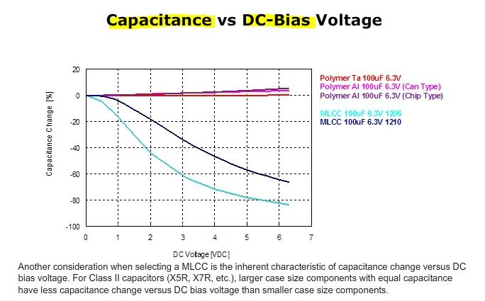
Furthermore, most types of MLCC capacitors suffer from known weaknesses – dependence of the capacity on applied voltage, and also not the best in class discharging curve. In other words, to get for example, true 100 μF at 12 volts, MLCC capacitor rated for 100 μF and 35-50 volts should be used. You will get much less than nominal capacity if you use 16 volts-rated capacitors at 12 volts which is a normal voltage for digital Z scale.
This diagram can be a brief illustration of what I am talking about:

Unfortunately, 100 μF MLCC capacitors rated for 35-50 volts don’t exist. 100 μF 16V in SMD 1206 or 1210 cases is the maximum we can get at the moment. There is also such a very important parameter as ESR, in which MLCCs are also not winning, but it is less critical for low-frequency usage.
Now we came to the following conclusion: if we want to get compact and effective power saving circuit, we have to switch to a different type of capacitors. Such type exists indeed, and it is also very cheap – it is can-type aluminum electrolytic capacitors. They feature very high density of stored energy in the given volume, and their capacity is actually independent of voltage. However, their size is way far from what is needed in Z scale.
Thus, we have to look further for a different solution. It exists as well – it is Tantalum capacitors. However, I always avoided using them in my projects due to a high flammability and sensitivity to the overvoltage and overheating. But the progress in technology never stops – now electronic manufacturers offer components with significantly improved characteristics, and modern Tantalum capacitors are not exclusion from the rule.
To be exact, we are talking about Tantalum Polymer capacitors which feature improved energy density and reliability in comparison to conventional Tantalum caps. In last years, major manufacturers such as Kyocera/AVX and Kemet introduced new series of Ta-Poly (Tantalum-Polymer) capacitors with excellent characteristics. Some of the models in their product ranges can be used in Z scale.
This diagram shows the main advantage of Tantalum Polymer capacitors – permanency of their capacity within all voltage range, up to the maximum rated voltage:
I chose 470 μF 16 V capacitors in SMD 7361-20 case from Kyocera/AVX (length 7.3 mm, width 6.1 mm, height 2 mm), Art. No TCN4477M016R0070E. This is the smallest and the most capacious model rated for 16 volts to date. It is worth noting that previous models of capacitors with the same parameters were available only in bulky 7343-43 and 7361-43 cases with 4.3 mm height. Additionally, new capacitors feature one of the lowest ESR values in class.
However, there is a biggest downside: these all-mighty caps are very expensive. Of course, each advantage and/or feature comes at a price, but these capacitors are being sold for almost 5 USD per piece before tax:
mou.sr/3w7xSk5Only bulk quantity can help to reduce it somehow. Here are some links for nerds:
Product page on official website:
www.kyocera-avx.com/products/polymer/tcn-series/Datasheet:
datasheets.kyocera-avx.com/TCN_Undertab.pdfGuidelines and Safety. This document can be useful for everyone who wants to understand why it is important to derate the nominal voltage. Also, differences between Ta-Poly and MLCC capacitors shown here very good:
www.kyocera-avx.com/docs/techinfo/Tantalum-NiobiumCapacitors/PolymerGuidelines.pdfDespite all obvious advantages, a special control circuit is needed to ensure safe and reliable operation of these capacitors. For this, I used a dedicated linear voltage stabilizer chip with low voltage dropout (LDO regulator). Along with keeping maximal voltage at the safe level, this chip also provides a thermal protection. Overcurrent and surge protection is provided by a series resistor and inductor.
As a result, we get a 100% safe and reliable power saving circuit that provides a very pronounced keep-alive effect to the motor and lights of the train model. It is also worth mentioning that these capacitors are also used in power-saving circuits of server-class hard disk drives and SSDs.
Practical tests showed significant progress in efficiency of buffering of the new circuit in comparison to the one based on MLCC capacitors. I used two 470 μF capacitors connected in parallel – as a result, we have almost 1000 μF buffer fully available at any voltage.
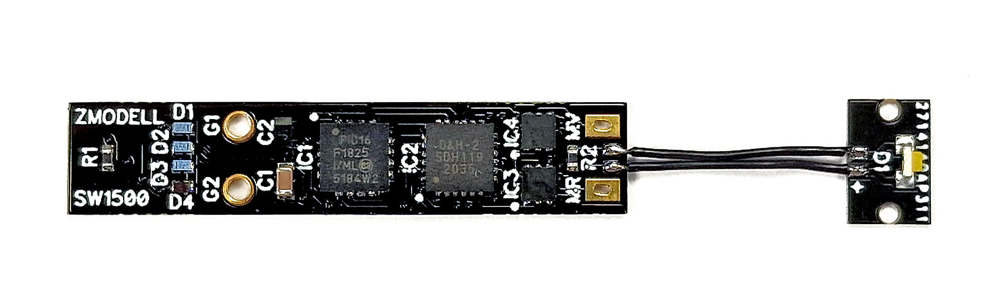
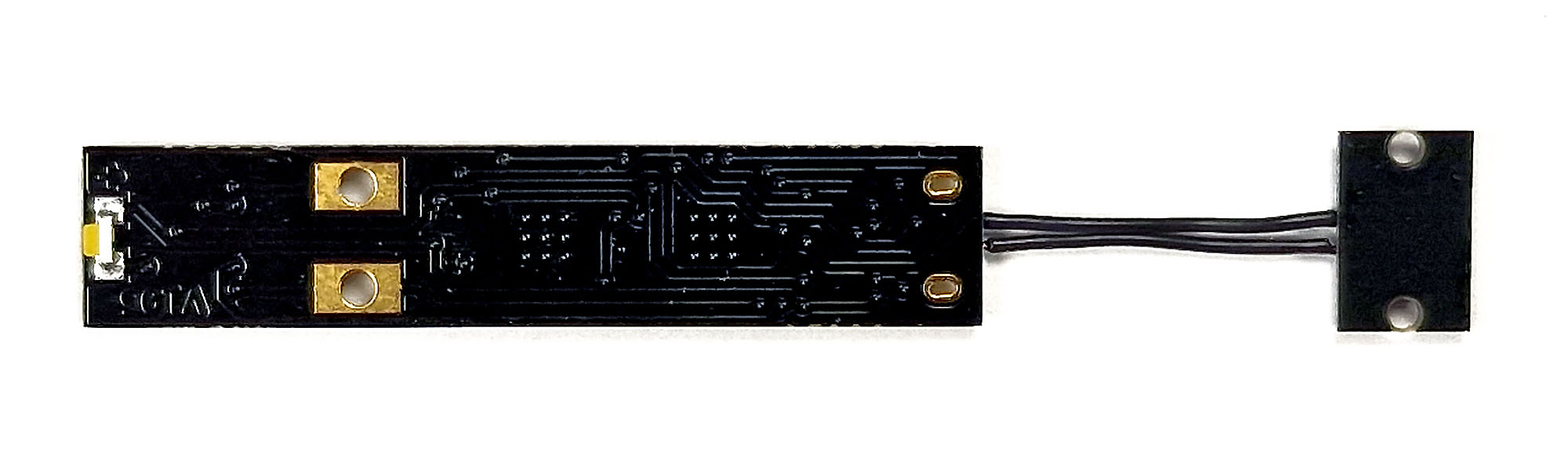
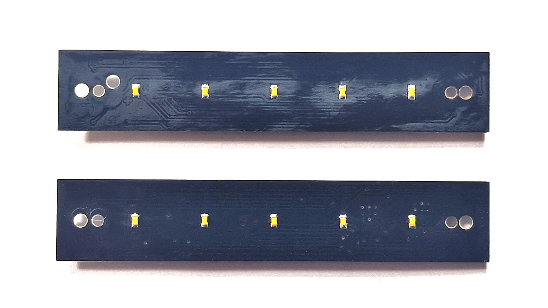
So, here are these decoders – VT98-A for the motor car and VT98-B for the trailing car:

Circuit boards feature warm white side glowing LEDs for upper headlights. I added 5x SMD 0402 warm white LEDs to the bottom side for smooth light distribution:
I also developed my own headlight and rear light circuit boards, as original boards do not provide red rear lights. Since no bi-color warm white/red side-glowing LEDs exist, I used pairs of separate SMD 0602 warm white and red side glowing LEDs soldered close to each other:

In order to provide separate control of all front and rear lights at the both ends of the car, I connected each of them to a separate output – LV, LR, AUX1 and AUX2. Such connection allows to switch off unnecessary lights between the cars when they drive in consist.
To control interior lighting, I used AUX3 5V logical output. It can be loaded with 20 mA max., but since 5x 0402 LEDs consume only around 3 mA in total, I connected them to AUX3 directly, without any external transistors, only with appropriate resistors in series.
However, AUX3 output cannot be dimmed. To eliminate this shortcoming, I added a very small adjustable resistor that allows the brightness of interior lighting to be adjusted. This resistor has a very small size – only 2x2.7 mm, the smallest available adjustable resistor on the market.
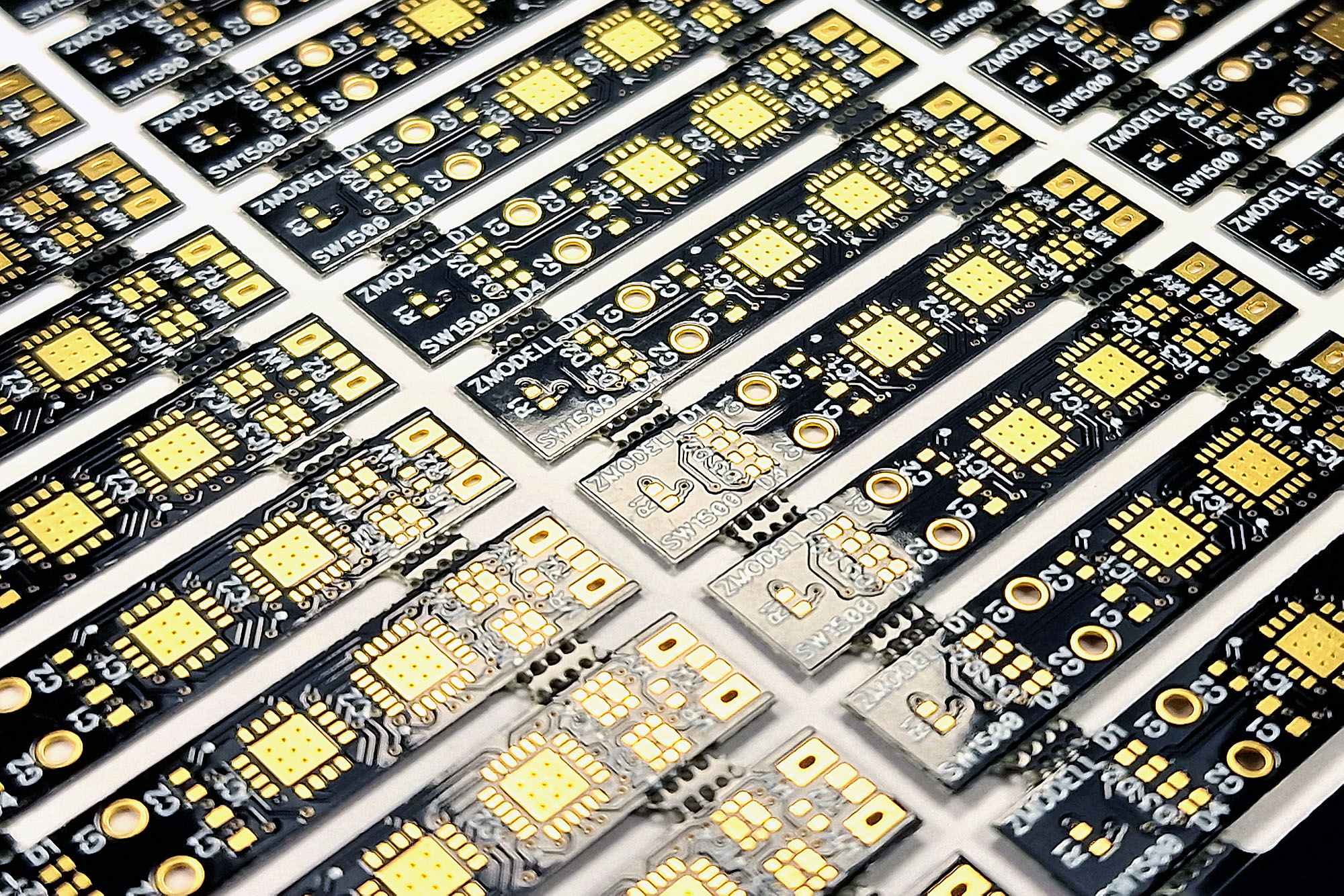
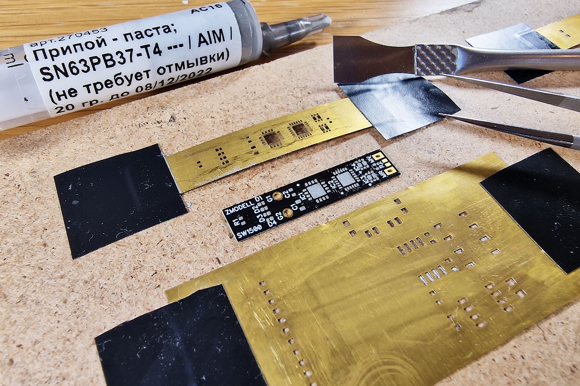
Both variants of the circuit boards have the same size – 50 x 9.5 mm. Population of electronic components is very dense. Tracing process in PCB design software refused to complete automatically, so I had to trace untraced nets manually. Luckily, I did it successfully. I used gold-plating during manufacturing of the circuit boards, as it significantly improves soldering quality of very small SMD components:

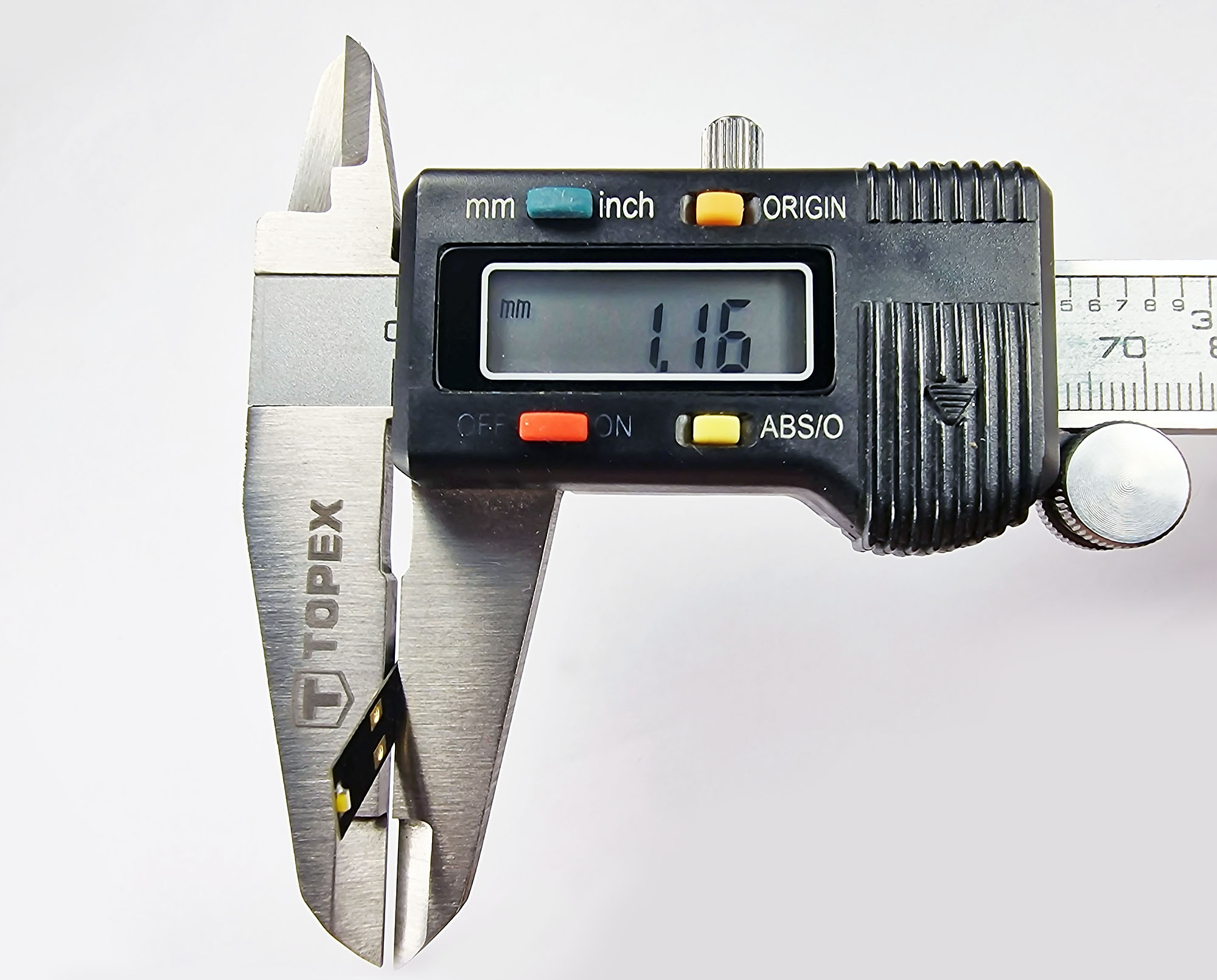
I was deeply concerned whether some thick components will fit under the roof inside the railbus. It became a big problem – even the thinnest available 2 mm buffer capacitors appeared to be too thick to let the housing sit on the chassis completely – there was a 0.3-0.4 mm gap remaining. To fix this, I decided to redesign the circuit boards. I reduced the thickness of circuit boards from 0.5 mm to only 0.2 mm, and also moved some components closer to the center, where the roof is the thickest.
Of course, 0.2 mm circuit boards are very flexible and more vulnerable; but it was the only way to fit all components inside such a limited space:

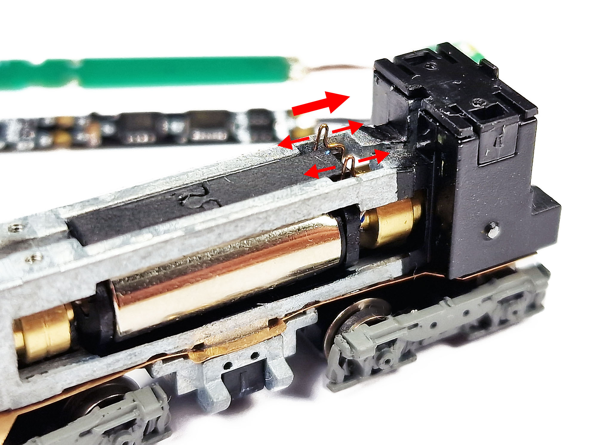
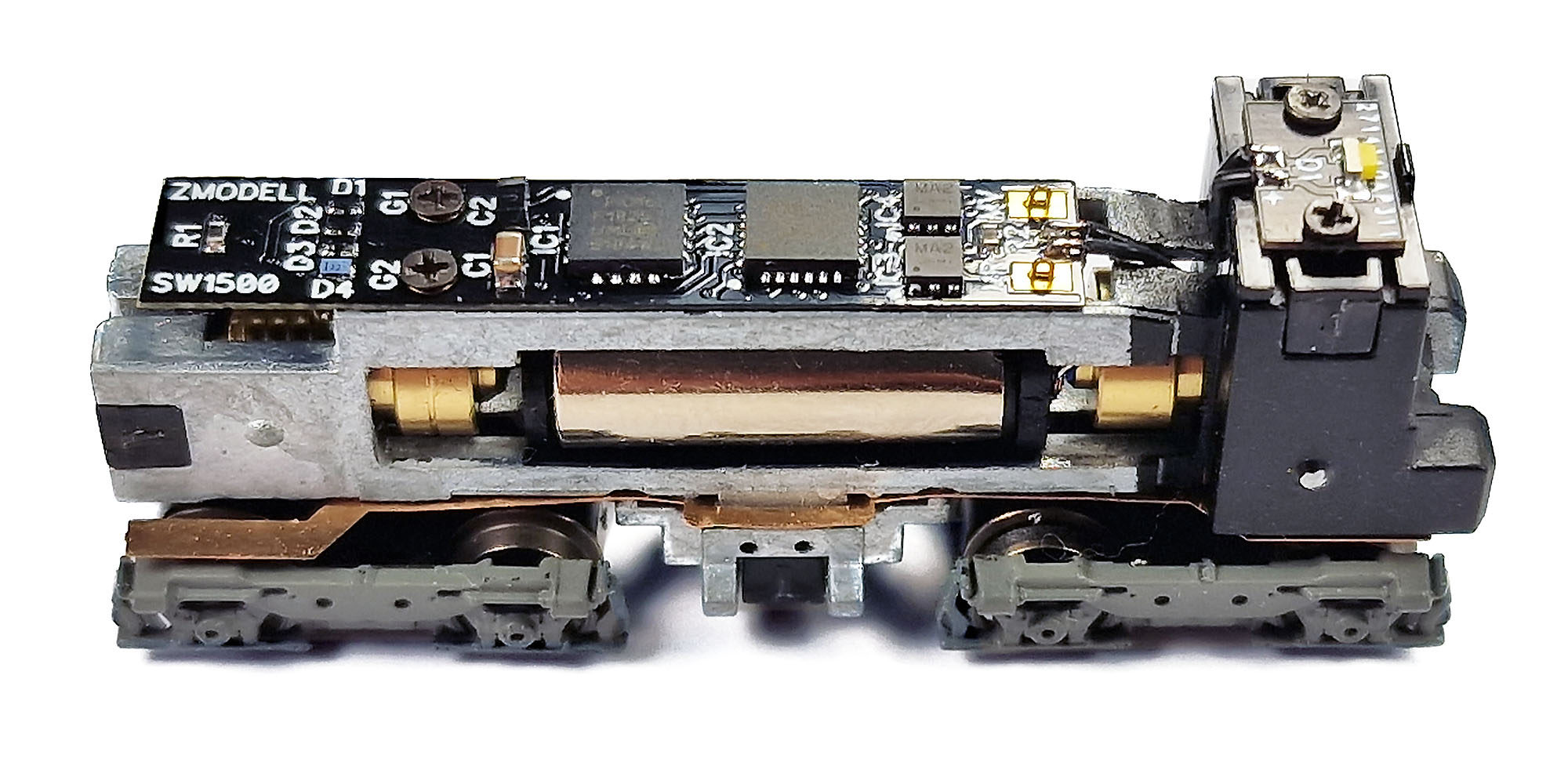
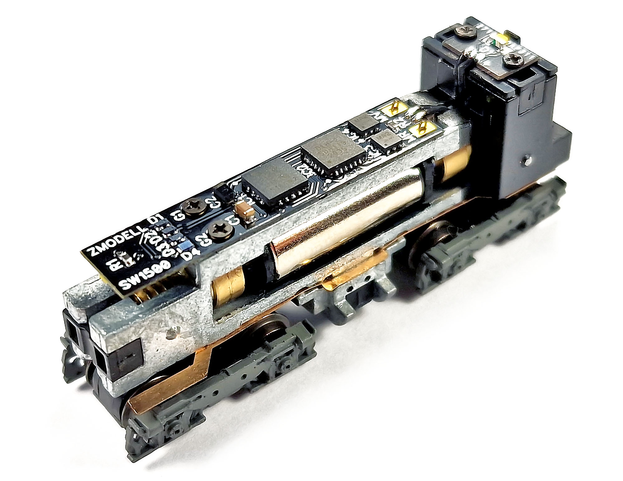
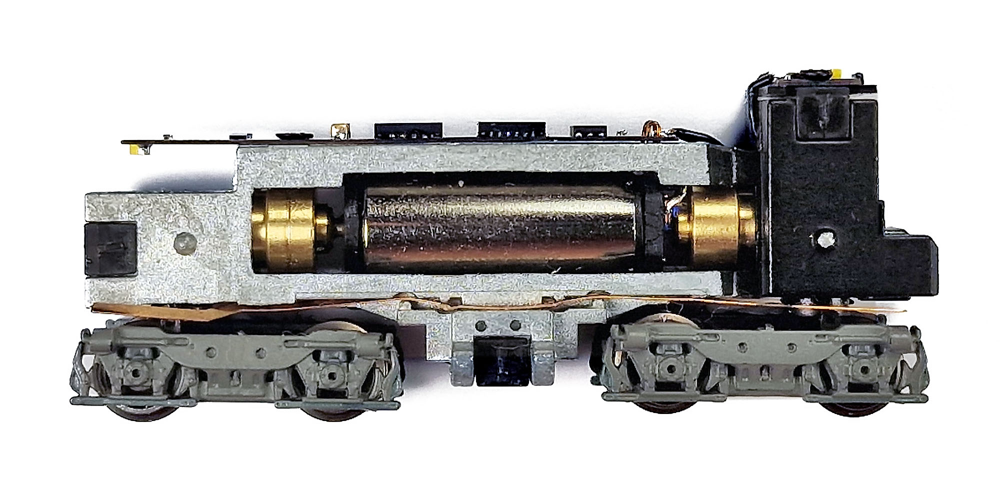
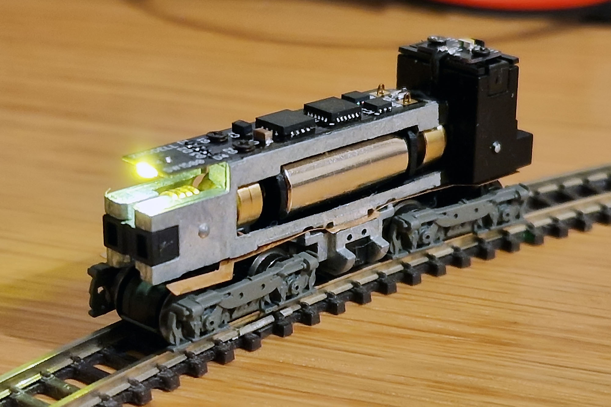
As for the installation process: in a couple of words, I can describe it as extremely complex, up to 20 points out of 10. Installation requires a lot of skills, precision and patience. Wiring is also very complex too. There are 12 different color wires in the motor car and 8 in the trailing car. I used 0.28 mm ultra-thin high-flexible multi-strand wires with PTFE coating. Here is how the decoder looks already installed onto the chassis:


But wonderful results justify all these numerous efforts completely – railbuses drive very smoothly and flawlessly, and interior lighting does not flicker at all. Furthermore, it continues glowing for a moment even after removal the car from the track – it proves very high efficiency of the power saving circuit.
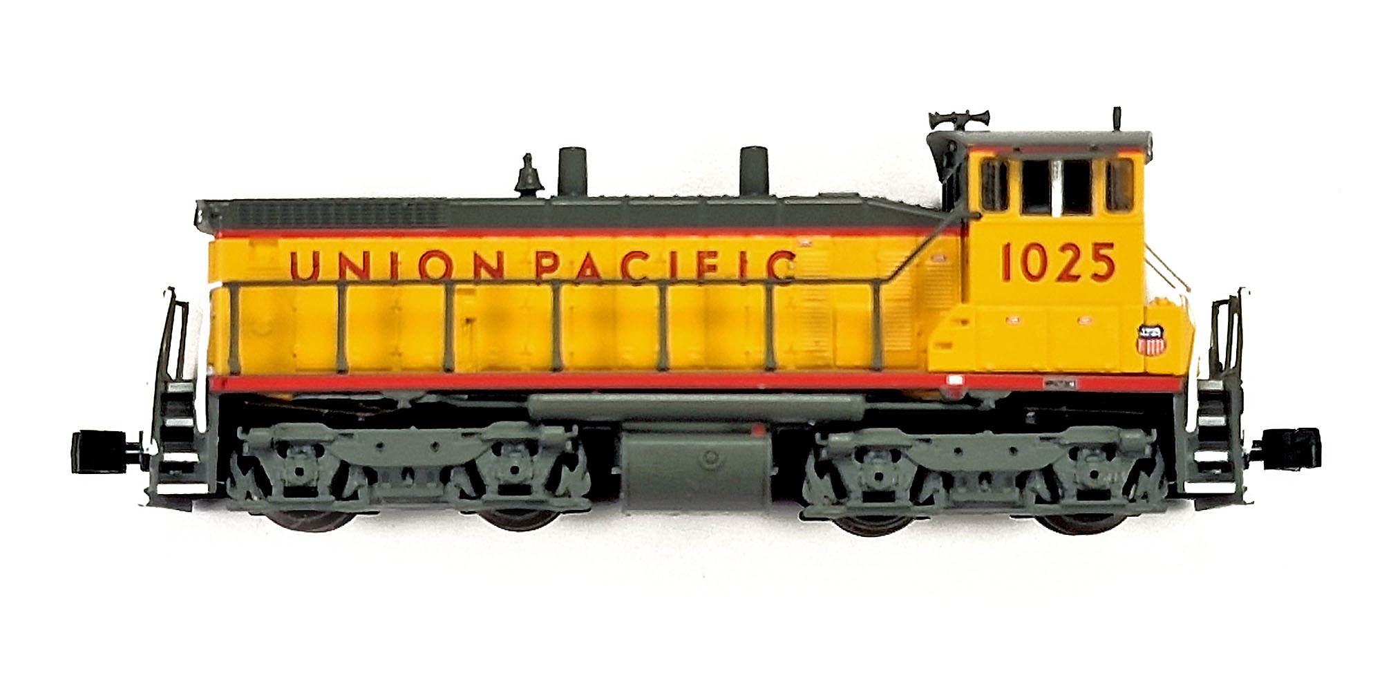
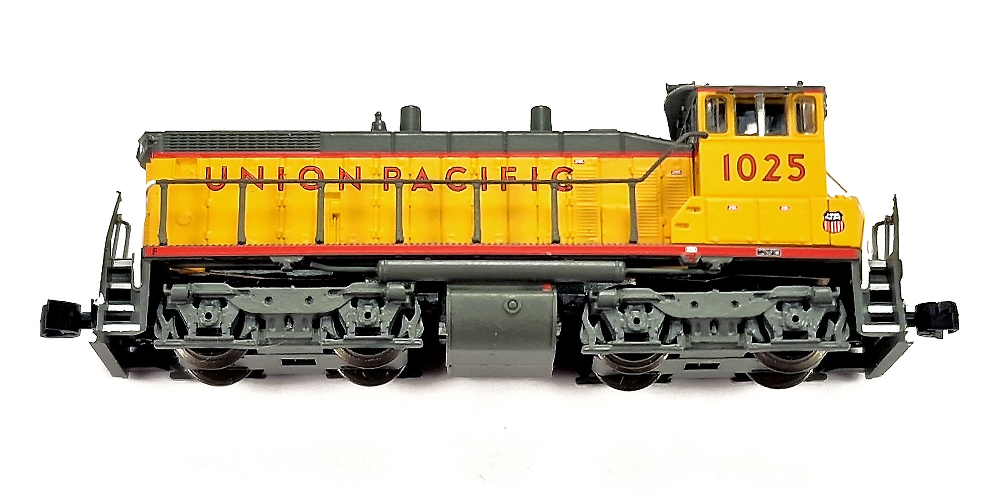
Here is how the newly digitized railbuses look in action:
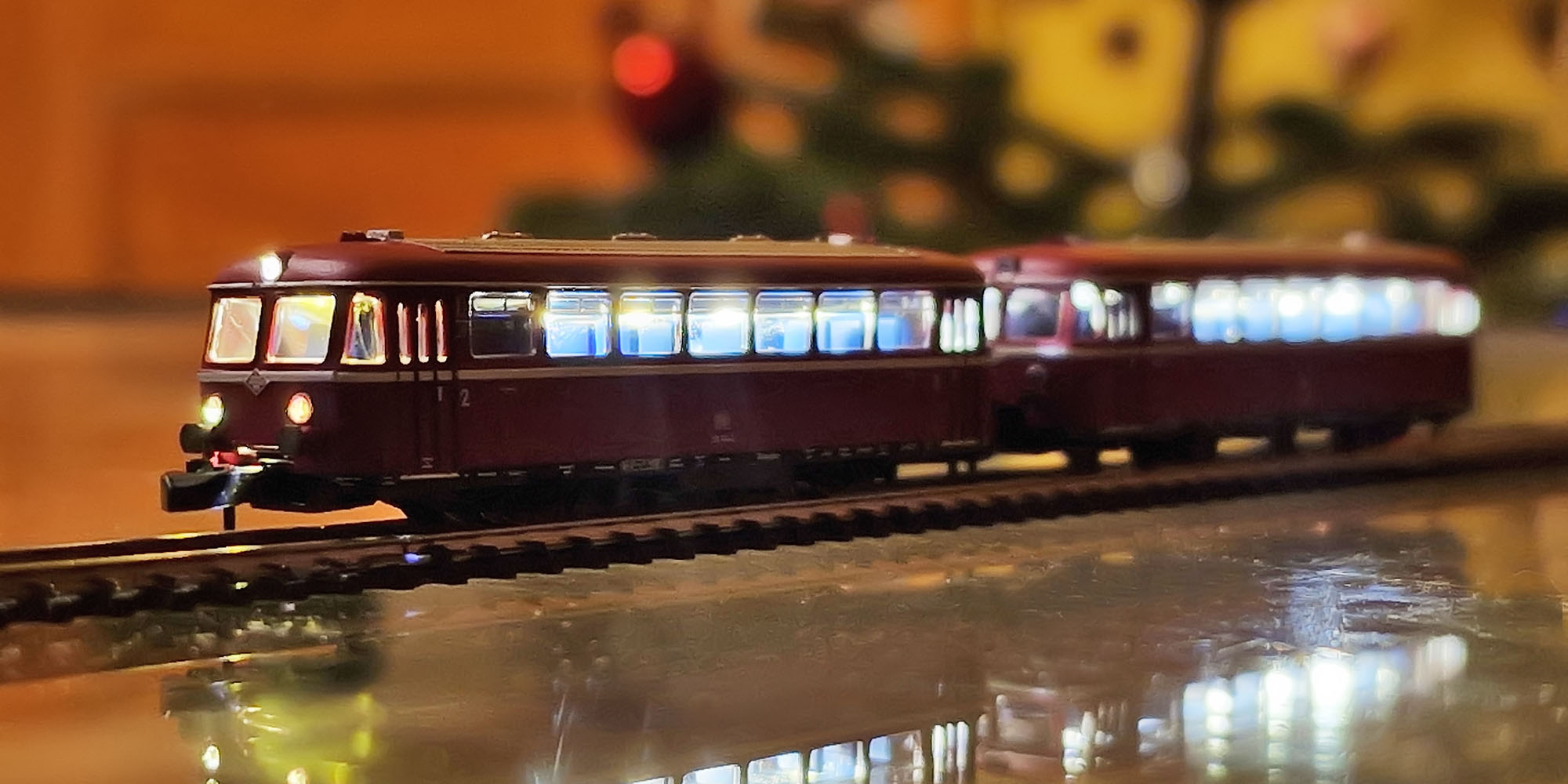
The same angle demonstrates working red rear lights:

I recorded a short video where you can see a pair of VT 98 railbuses from Märklin 88167 set driving very smoothly at the very low speed:
The set can be enhanced further by connecting two railbuses permanently with a drawbar and providing cable connection between the cars that will allow to improve electric contact with the tracks even more.
Later, I decided to fix one very visible weakness of the model: unwanted light leakage from the coupler opening. It is quite annoying visually, as the railbus looks like a "light box". It is strange why Märklin refused to work on this, as they pay good attention to the light isolation in their last models.
I made special inserts from black 1.5 mm foamed EVA and attached them to the ends of chassis with a double-sided adhesive tape:
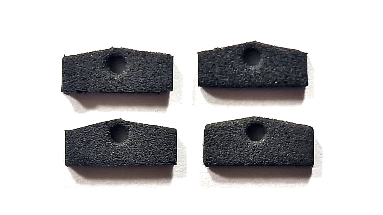

Now the problem solved completely, and digitized railbuses became even closer to perfection.
I would also like to express my sincere gratitude to the Doehler & Haass company for invaluable technical assistance during development of this product.
Best regards,
Alex