

Zmodell energy storage module ZM-ESM-01
Jul 24, 2024 16:11:12 GMT -5
Kez, BAZman, and 7 more like this
Post by scanrail on Jul 24, 2024 16:11:12 GMT -5
Greetings to all,
I would like to introduce a small but useful electronic accessory that may become a good companion to my small digital decoder ZM05A and also to any other digital decoder – energy storage module ZM-ESM-01.
As many already know, the quality of electric contact between the tracks and wheelsets is often a big problem in Z scale due to the limitations of size and weight of the vehicles. The locomotives may often stop on dirty tracks or on any potential problematic sections like turnouts, crossovers, rail joints and so on. The problem is even more pronounced with the steam locomotives which often have only 3 powered axles.
The same issue often causes light flickering in passenger cars fitted with interior lighting, especially in digital mode. It is also not a secret that reliable power buffering is much recommended for sound decoders for clean and stable sound output.
Although power buffering devices already exist in many variations, my intention was still to bring something new in this area, based on the experience in developing numerous digital solutions and a good knowledge of requirements of Z scale. Successful integration of the very compact energy storage modules based on new Tantalum Polymer capacitors into a number of digital decoders for Z scale vehicles brought me an idea to develop a standalone module that can be used with any digital decoder which offers a possibility of connecting external capacitors.
Most types of capacitors have one big advantage over ceramic (MLCC) Class II – unlike the last one, their capacity does not depend on applied voltage (this negative effect is also called “DC bias”). Capacity of ceramic capacitors decreases significantly when applied voltage is close to nominal. Thus, using them as energy storage devices has quite mediocre efficiency. In my own experience, ceramic capacitors do perform quite well only in the circuits with very low power consumption – such as interior lighting boards, where each of the LEDs often consumes not more than only 1 mA.
Using ceramic capacitors for storing backup energy for the motor in the locomotive is therefore much less efficient. Some capacitor theory can be found in my report about digital decoder for VT98 railbus.
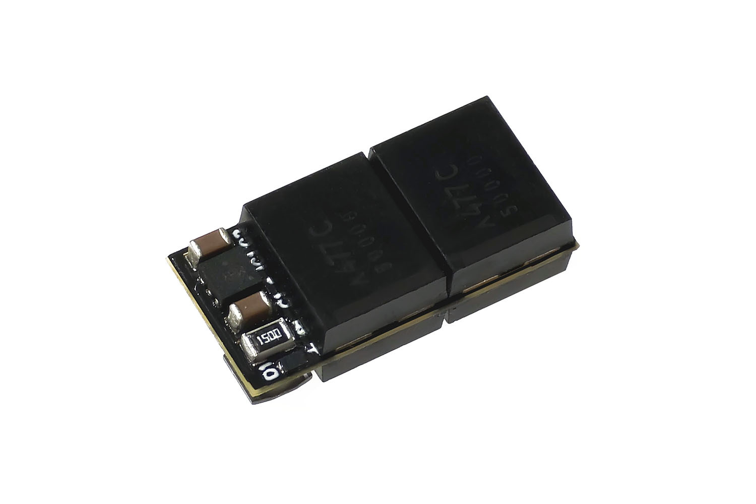
My new energy storage module is intended to solve this problem, and it is based on highly efficient Tantalum Polymer capacitors. The board contains 4x 470 µF/16V capacitors with the highest energy density currently on the market and offers as much as 1880 µF total capacity:
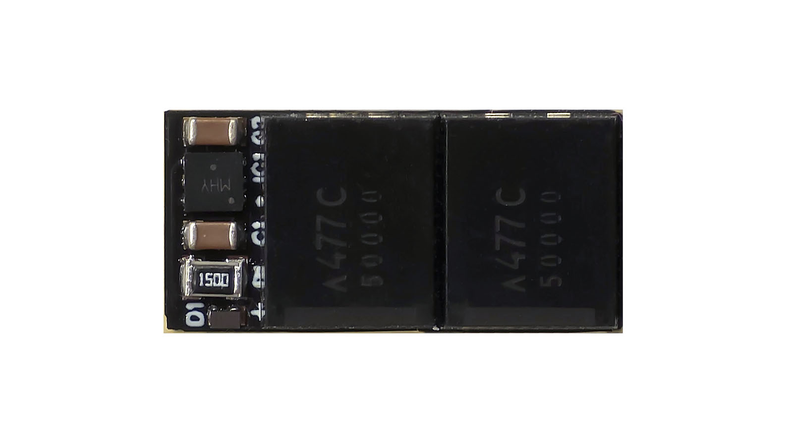
The module also has thermal and overvoltage protection. The last feature is very important for Tantalum capacitors which are very sensitive to excessive voltage. Additionally, Tantalum Polymer capacitors are in general safer than normal Tantalum models as such. The module contains inductor that provides compatibility with asymmetric braking sections and helps eliminating potential issues in programming mode on certain systems.
Energy storage module comes with 10 cm thin flexible cables and it is sealed in thin shrinking tube for additional safety:
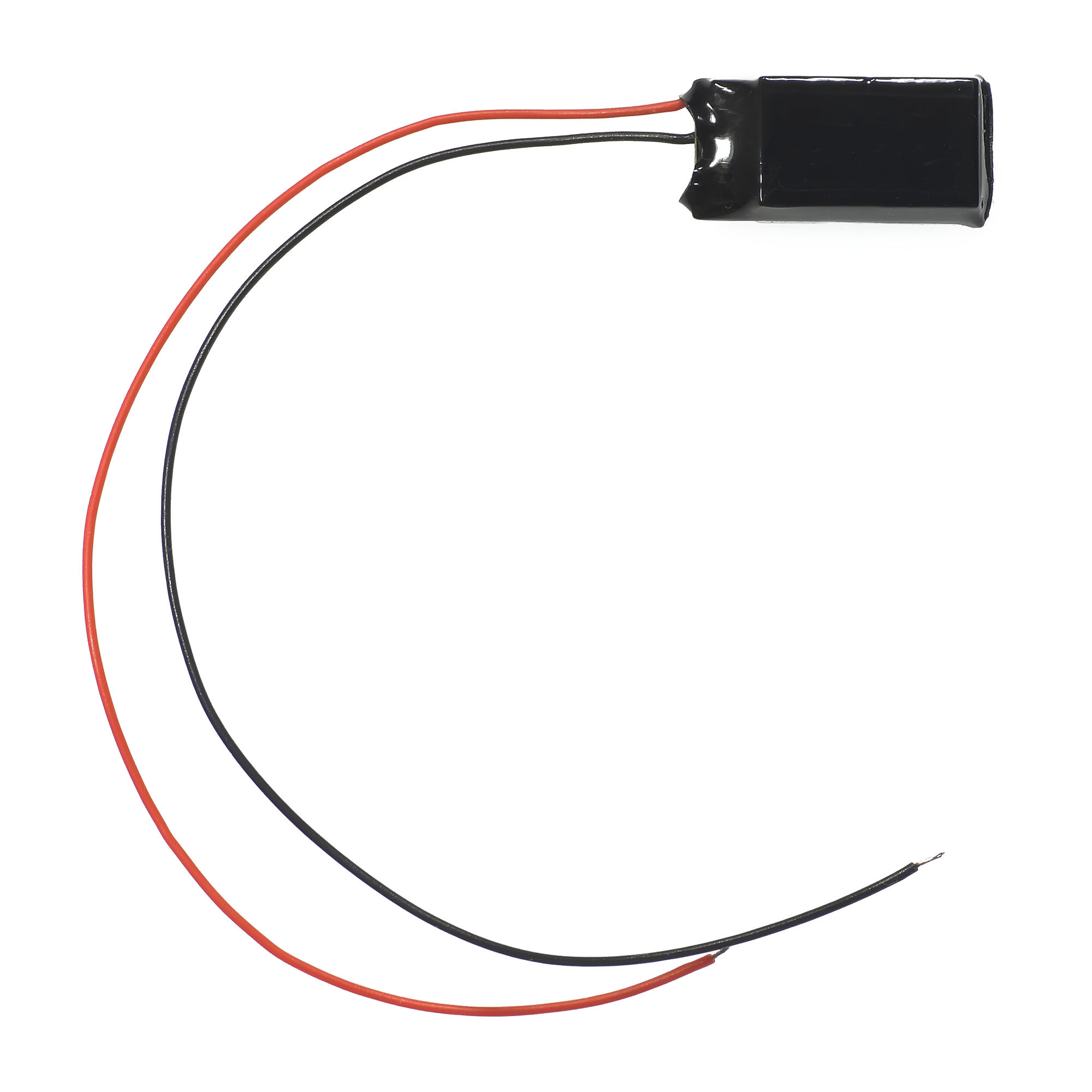
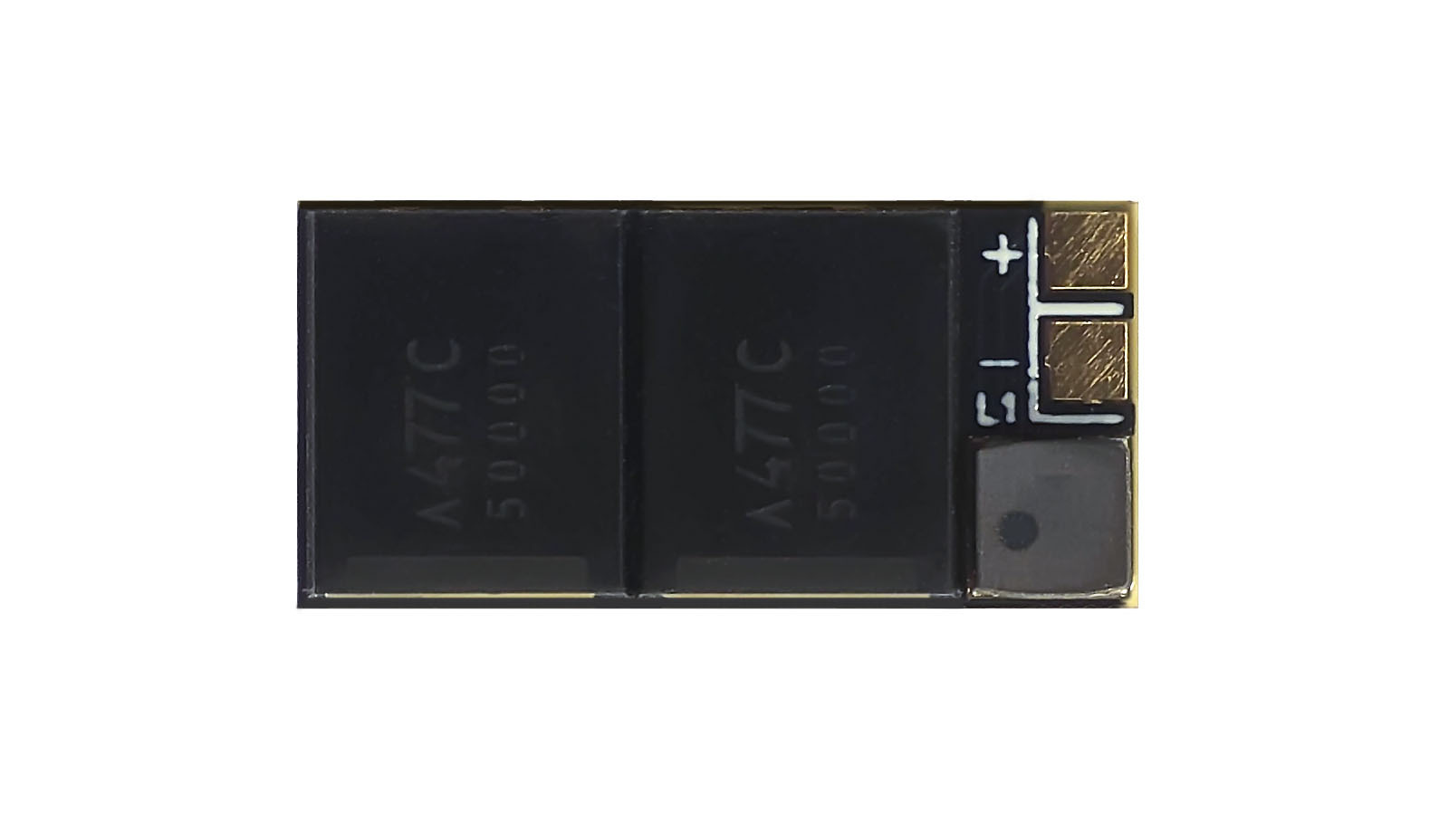
Connection to the digital decoder is very easy – red wire should be connected to VS (“Voltage Supply”) pad, while black wire – to GND (“Ground”) pad. If the digital decoder offers a special pad for connecting positive output of the power storage module (often called “Vcap”), then the red wire should be connected to it. Additional information on possible methods of connection can be found in downloadable user’s manual in this thread.
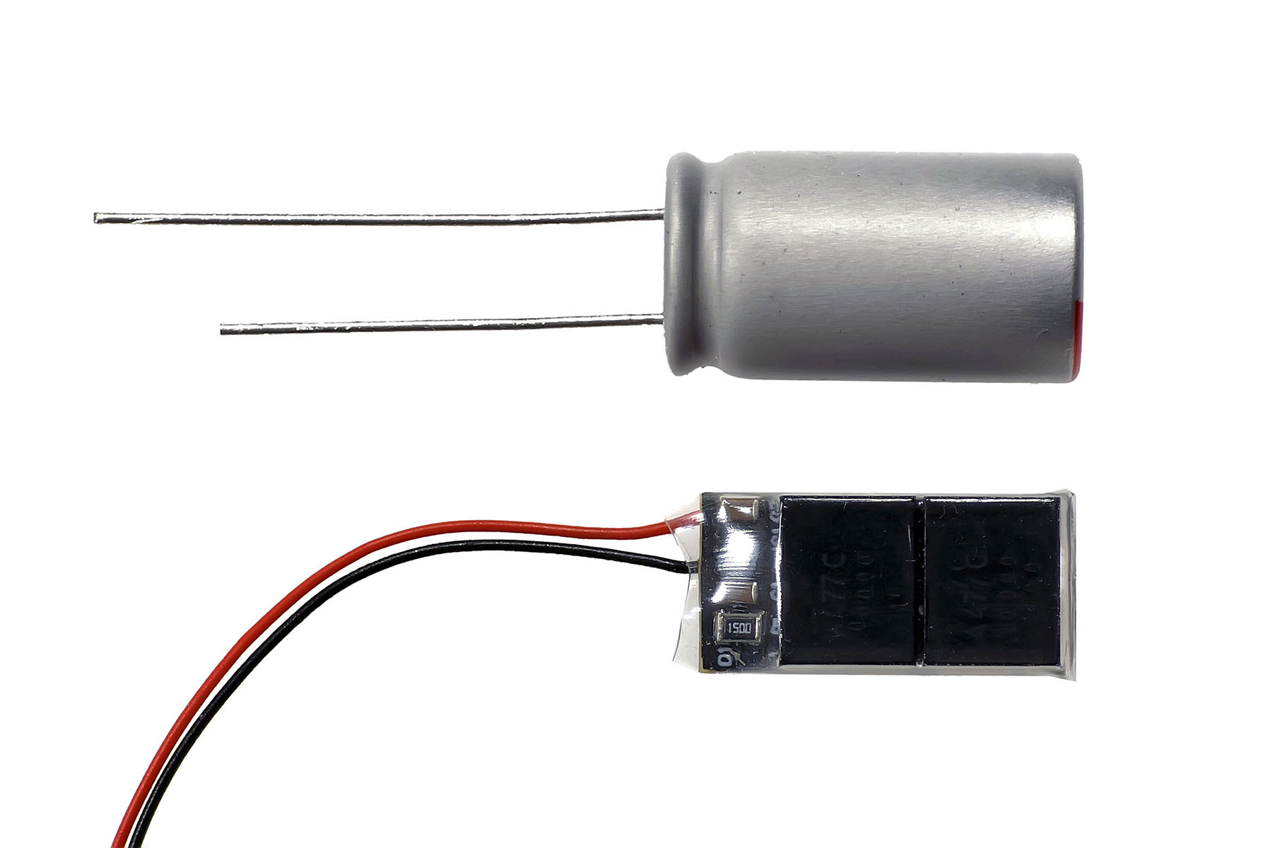
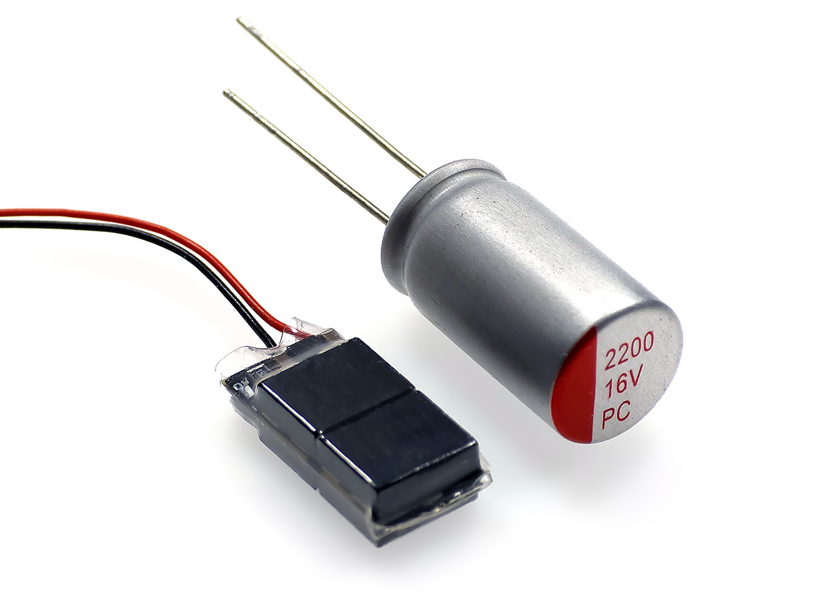
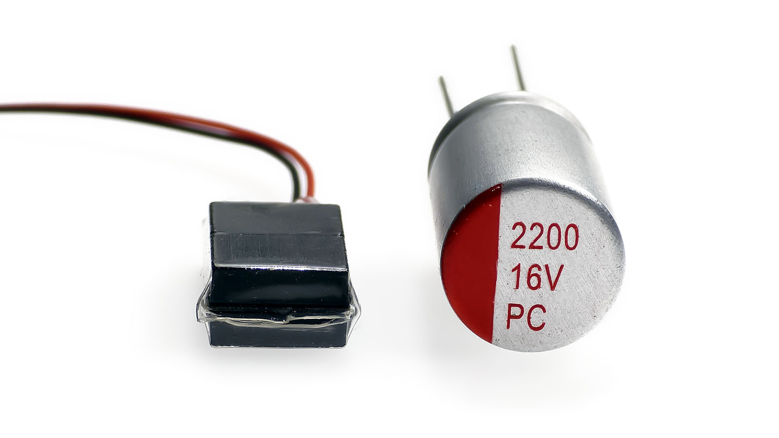
The size of energy storage module is very small (in relation to the total capacity) – only 16 x 7.8 x 4.5 mm. In order to show the difference, I decided to compare my module with 2200 µF/16V can-type electrolytic organic polymer capacitor which has a very high energy density, too and has a size of 18x10 mm (most other electrolytic capacitors with the same characteristics are bigger). Just look at these pictures – my module featuring almost the same capacity is noticeably smaller than this electrolytic capacitor itself. And my module already has all necessary components onboard, while the single capacitor still needs some external components to be connected to the digital decoder:
Of course, the charging current is limited to 100 mA according to NEM standards. Energy storage module can be fitted in the tenders of most Z scale locomotives, but of course, the scope of possible use in not limited by this.
The maximum input voltage is 30V, while output is limited to 14.5 volts.
Practical measurements of the buffering time showed the following values at 12-14 volts DCC track voltage:
- 0.3-0.5 seconds for locomotives with DC brushed motors (Z scale locomotive with 5-pole motor was used for testing)
- 0.5-1 seconds for locomotives with coreless motors (Z scale locomotive with coreless motor was used)
- 2-4 seconds for LED interior lighting boards (function decoder + chain of 10-12 warm white SMD 0402 LEDs consuming 1 mA each)
Of course, these are approximate values. They may differ, depending on the type and efficiency of the motor and the track voltage. The higher the track voltage, the more efficient energy storage module is.
Don’t be scared by the values and don’t think that the buffering time is too short. First of all, even 0.1 second of buffering time is already helpful and prevents the digital decoder from too frequent restarting (if you aren’t sure – use oscilloscope and look at the picture with own eyes). Second, these values are REAL. If someone tells you that he runs his locomotive for 2 seconds with only one 1000 µF capacitor – don’t believe him, it is not true.
User’s Manual can be downloaded here:
ZM-ESM-01_EN.pdf (247.98 KB)
Each module is thoroughly tested on laboratory equipment for compliance to all designed parameters. A set of 2x ultra-thin (only 0.05 mm) double sided adhesives for mounting comes in the package.
Best regards,
Alex
I would like to introduce a small but useful electronic accessory that may become a good companion to my small digital decoder ZM05A and also to any other digital decoder – energy storage module ZM-ESM-01.
As many already know, the quality of electric contact between the tracks and wheelsets is often a big problem in Z scale due to the limitations of size and weight of the vehicles. The locomotives may often stop on dirty tracks or on any potential problematic sections like turnouts, crossovers, rail joints and so on. The problem is even more pronounced with the steam locomotives which often have only 3 powered axles.
The same issue often causes light flickering in passenger cars fitted with interior lighting, especially in digital mode. It is also not a secret that reliable power buffering is much recommended for sound decoders for clean and stable sound output.
Although power buffering devices already exist in many variations, my intention was still to bring something new in this area, based on the experience in developing numerous digital solutions and a good knowledge of requirements of Z scale. Successful integration of the very compact energy storage modules based on new Tantalum Polymer capacitors into a number of digital decoders for Z scale vehicles brought me an idea to develop a standalone module that can be used with any digital decoder which offers a possibility of connecting external capacitors.
Most types of capacitors have one big advantage over ceramic (MLCC) Class II – unlike the last one, their capacity does not depend on applied voltage (this negative effect is also called “DC bias”). Capacity of ceramic capacitors decreases significantly when applied voltage is close to nominal. Thus, using them as energy storage devices has quite mediocre efficiency. In my own experience, ceramic capacitors do perform quite well only in the circuits with very low power consumption – such as interior lighting boards, where each of the LEDs often consumes not more than only 1 mA.
Using ceramic capacitors for storing backup energy for the motor in the locomotive is therefore much less efficient. Some capacitor theory can be found in my report about digital decoder for VT98 railbus.
My new energy storage module is intended to solve this problem, and it is based on highly efficient Tantalum Polymer capacitors. The board contains 4x 470 µF/16V capacitors with the highest energy density currently on the market and offers as much as 1880 µF total capacity:
The module also has thermal and overvoltage protection. The last feature is very important for Tantalum capacitors which are very sensitive to excessive voltage. Additionally, Tantalum Polymer capacitors are in general safer than normal Tantalum models as such. The module contains inductor that provides compatibility with asymmetric braking sections and helps eliminating potential issues in programming mode on certain systems.
Energy storage module comes with 10 cm thin flexible cables and it is sealed in thin shrinking tube for additional safety:
Connection to the digital decoder is very easy – red wire should be connected to VS (“Voltage Supply”) pad, while black wire – to GND (“Ground”) pad. If the digital decoder offers a special pad for connecting positive output of the power storage module (often called “Vcap”), then the red wire should be connected to it. Additional information on possible methods of connection can be found in downloadable user’s manual in this thread.
The size of energy storage module is very small (in relation to the total capacity) – only 16 x 7.8 x 4.5 mm. In order to show the difference, I decided to compare my module with 2200 µF/16V can-type electrolytic organic polymer capacitor which has a very high energy density, too and has a size of 18x10 mm (most other electrolytic capacitors with the same characteristics are bigger). Just look at these pictures – my module featuring almost the same capacity is noticeably smaller than this electrolytic capacitor itself. And my module already has all necessary components onboard, while the single capacitor still needs some external components to be connected to the digital decoder:
Of course, the charging current is limited to 100 mA according to NEM standards. Energy storage module can be fitted in the tenders of most Z scale locomotives, but of course, the scope of possible use in not limited by this.
The maximum input voltage is 30V, while output is limited to 14.5 volts.
Practical measurements of the buffering time showed the following values at 12-14 volts DCC track voltage:
- 0.3-0.5 seconds for locomotives with DC brushed motors (Z scale locomotive with 5-pole motor was used for testing)
- 0.5-1 seconds for locomotives with coreless motors (Z scale locomotive with coreless motor was used)
- 2-4 seconds for LED interior lighting boards (function decoder + chain of 10-12 warm white SMD 0402 LEDs consuming 1 mA each)
Of course, these are approximate values. They may differ, depending on the type and efficiency of the motor and the track voltage. The higher the track voltage, the more efficient energy storage module is.
Don’t be scared by the values and don’t think that the buffering time is too short. First of all, even 0.1 second of buffering time is already helpful and prevents the digital decoder from too frequent restarting (if you aren’t sure – use oscilloscope and look at the picture with own eyes). Second, these values are REAL. If someone tells you that he runs his locomotive for 2 seconds with only one 1000 µF capacitor – don’t believe him, it is not true.
User’s Manual can be downloaded here:
ZM-ESM-01_EN.pdf (247.98 KB)
Each module is thoroughly tested on laboratory equipment for compliance to all designed parameters. A set of 2x ultra-thin (only 0.05 mm) double sided adhesives for mounting comes in the package.
Best regards,
Alex


 ? What exactly is you issue anyway?


