

Zmodell SC-2000 - digital programmable PWM speed controller
Aug 11, 2023 12:38:28 GMT -5
Kez, tjdreams, and 3 more like this
Post by scanrail on Aug 11, 2023 12:38:28 GMT -5
Greetings to all,
I would like to reveal one more development that I started back in Ukraine, but managed to finish only recently due to the lack of time and complexity of the project. It is a second generation of the digital programmable PWM speed controller Zmodell SC-1000 I presented 3 years ago: azlforum.com/thread/1698/zmodell-digital-programmable-speed-controller. Along with more sophisticated design, the new construction features a number of major updates and new features and received a designation SC-2000:

Like the first version, the new model is capable of controlling any kinds of locomotives of all scales from Z to G equipped with both conventional DC brushed motors as well as with coreless motors.
List of features
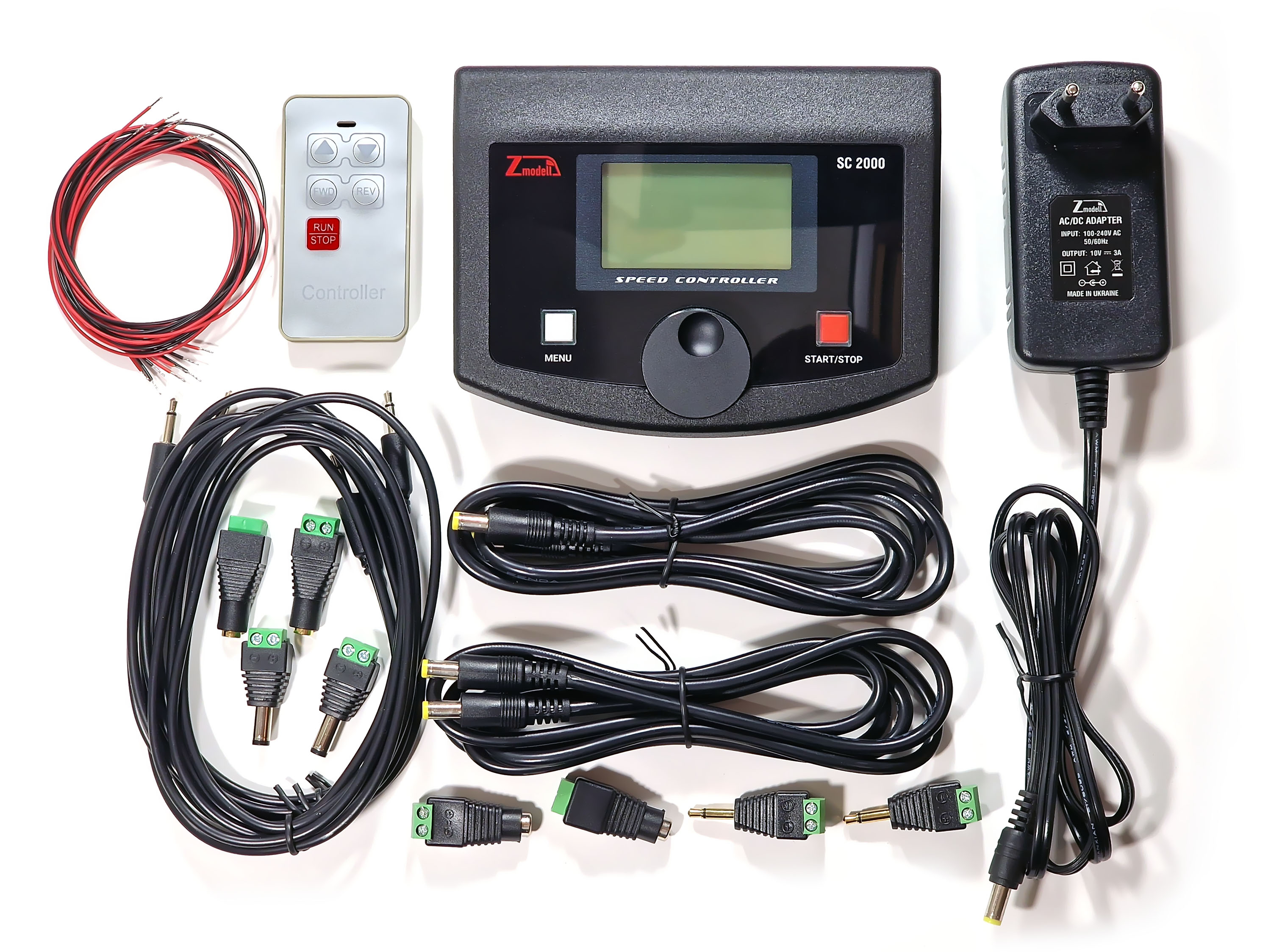
Package list
Here is a visual comparison of the new SC-2000 controller with its predecessor, SC-1000:

Differences from previous model
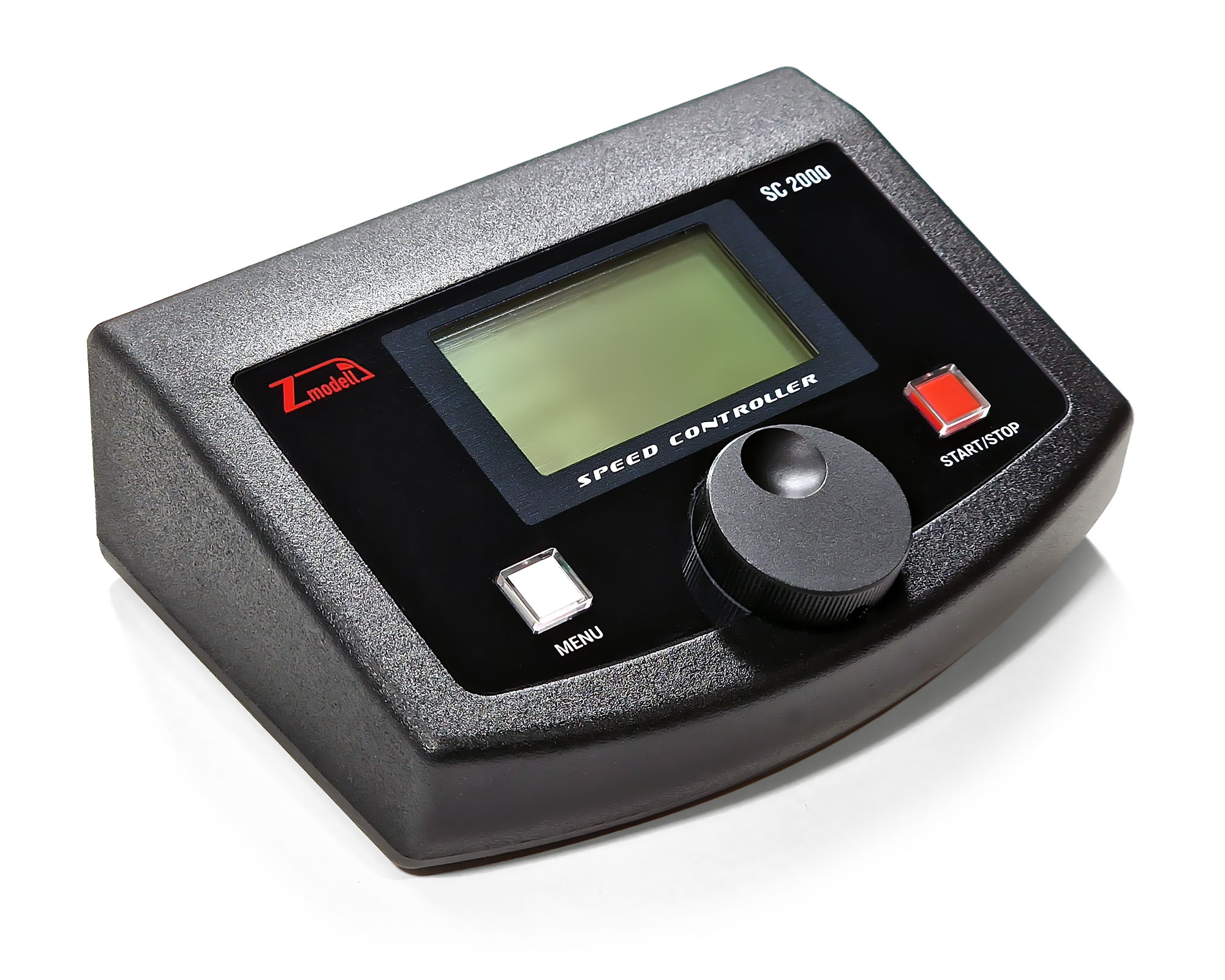
New rotary control knob
I decided to change the way of controlling the driving speed and direction to more intuitive and ergonomic. Three push buttons “UP”, “DOWN” and “DIRECTION” were replaced with a single rotary knob combined with a push button. Actually, this became to me the first reason to develop a new version of device – to equip it with digital rotary controller widely used in different power supplies and digital command stations.
For this reason, I developed a special module that converts signals from the digital encoder to the two individual switching lines that can replace “UP” and “DOWN” buttons. Used digital encoder is also combined with a push button that replaces “DRIVING DIRECTION” in my case. Digital encoder is a mechanical device similar to analog potentiometers that produces two series of switching impulses shifted with each other by a half-length of a single impulse):

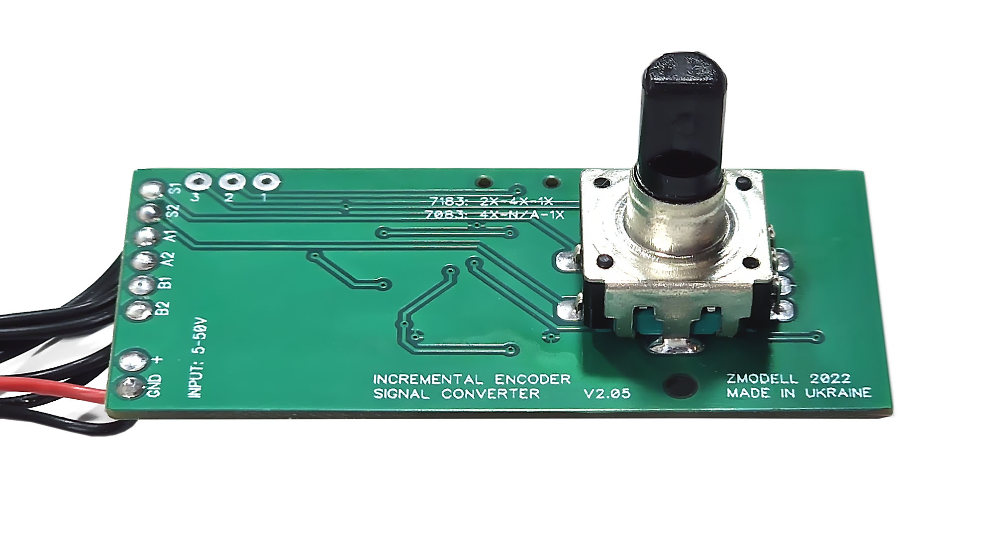
New rotary knob allows not only to control the speed and direction of the train, but also adjusting settings in device’s menu. It is made of high-quality black anodized aluminum.
Remote control
PWM module used in my device supports remote control via radio channel. This way of wireless connection has an obvious advantage: user does not have to care about direct visibility between the remote control and the main device and can focus solely on controlling the train, regardless of the position in the room.
So far, I decided to use existing model of remote control that is suitable to my PWM controller. I plan to develop my own remote control in the future – more advanced, and also featuring very convenient and ergonomic rotary knob instead of buttons. Current model of remote control is powered by a single CR2032 battery.
Support of starting and ending points
PWM controller offers one more new feature – support of forward and reverse stop points with a help of sensors. Any kind of normally open mechanical switch, optocoupler switch, Hall sensor or reed switch can be used for this purpose.
With this new feature, it is very easy to set up a shuttle operation between two stations on the layout. Furthermore, it can be now set up in two different ways: using preprogrammed values (setting time and speed for forward, stop and reverse) and also with a help of sensors. For example, the train departs from the first station, reaches the sensor at the second station and stops there, waits for a predefined period of time and then starts driving in reverse direction until it reaches the sensor at the first station and stops there once again.
Controller offers 4 different modes:
1. No stop points. Sensors are not used.
2. The train starts forwards, reaches forward sensor and stops there.
3. The train starts forwards, reaches forward sensor and stops there. Then it starts in reverse direction, reaches reverse sensor and stops there.
4. Loop operation: The train starts forwards, reaches forward sensor and stops there. Then it starts in reverse direction, reaches reverse sensor and stops there. After this, the cycle repeats again until the stop button is pressed.
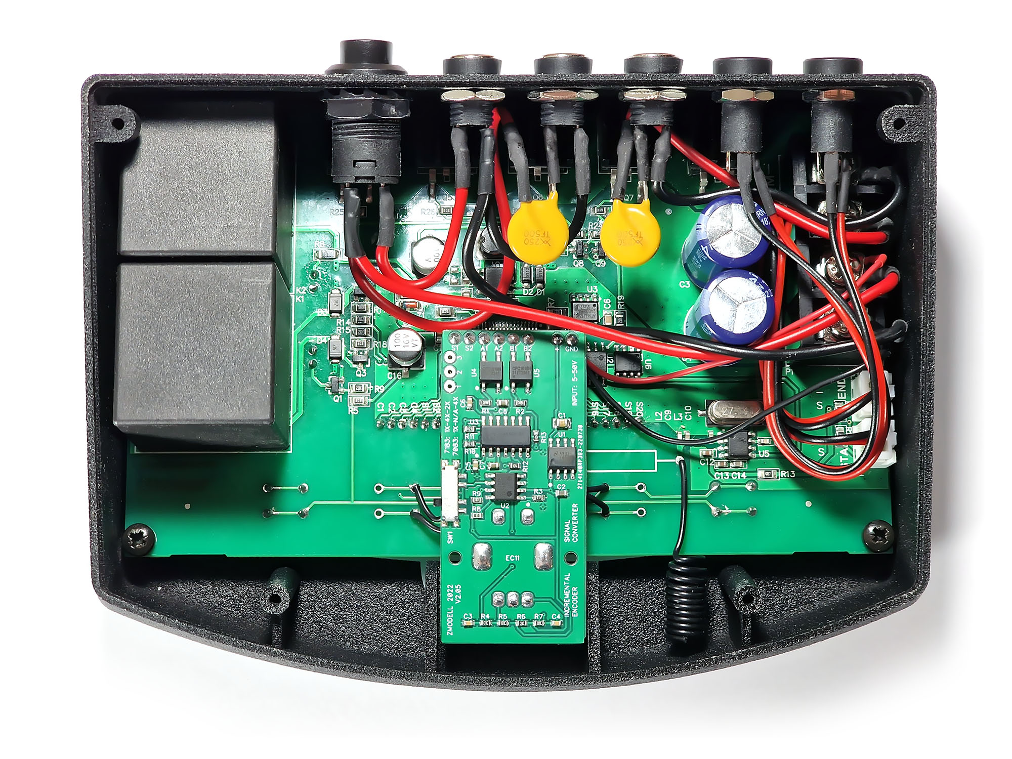
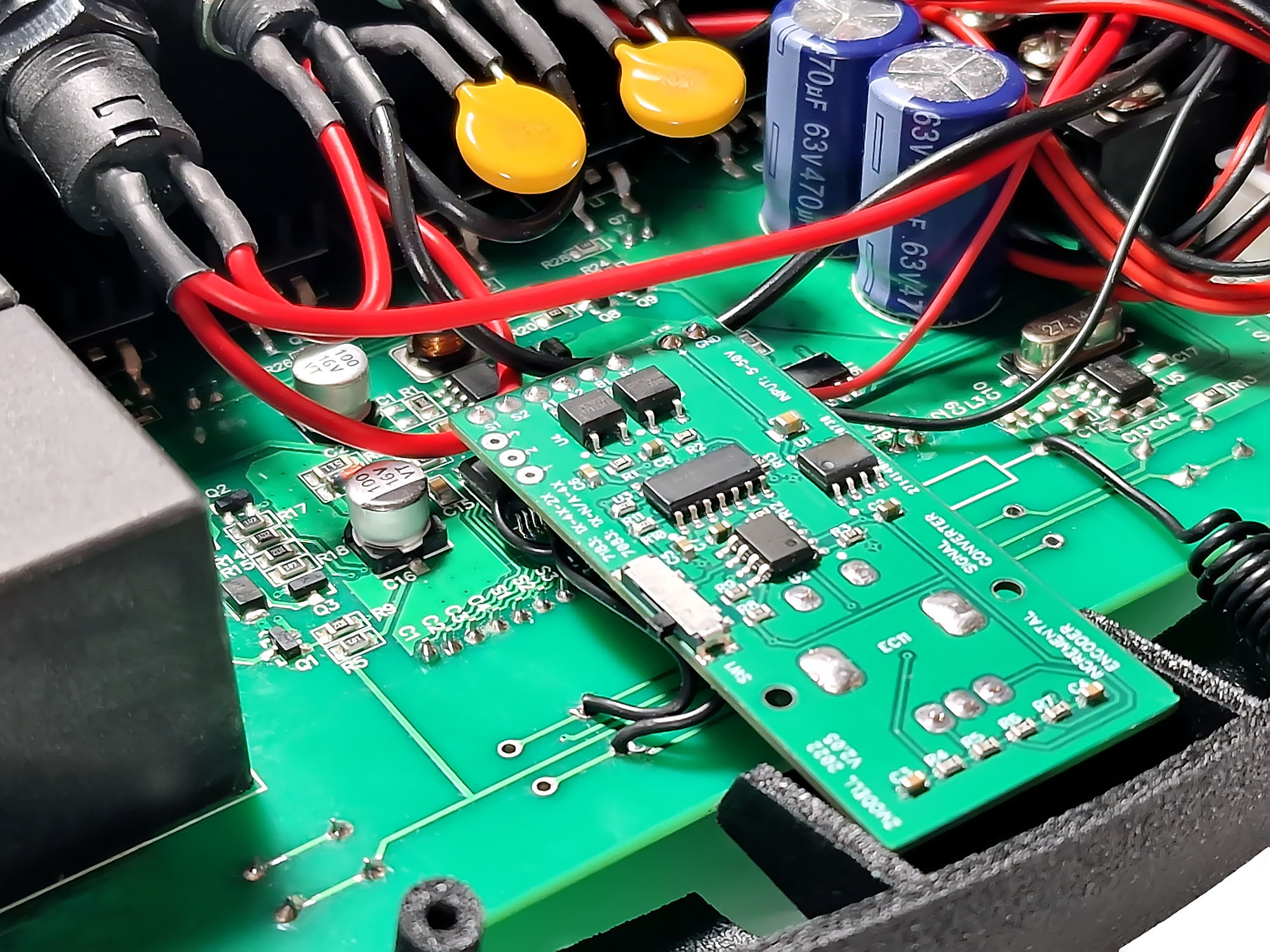
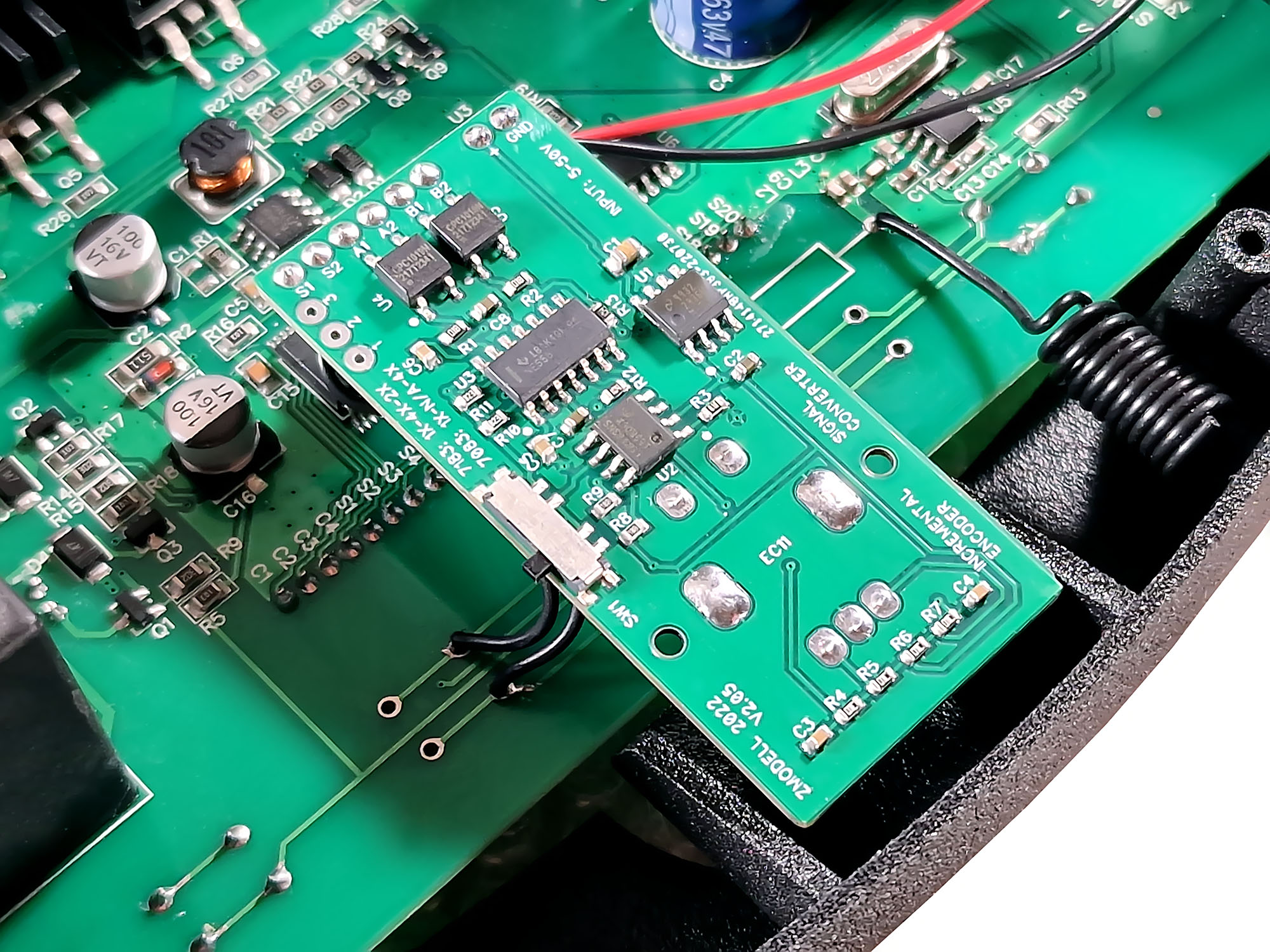
Here is what’s inside the device:
Functions of controls:
Modes and settings
Device works in three modes – Manual, Auto and Programming. In manual mode, “MANU” sign and speed (in %) indicated on the screen. Also, current direction of travel (“FWD”/”REV”) and total running time is shown.
In Auto mode, “AUTO” sign, speed and current direction of travel (“FWD”/”REV”) are indicated. Countdown timer in the numeric section shows remaining time of the current operation (forward, reverse driving or pause).
Pressing “MENU” button enters settings and programming menu. Continuous pressing of this button scrolls the list of available settings and programmable functions. Here is a list of them:
Note: Automatic mode is possible only when the stop sensors are not used (function E set to 1). Forward and reverse speed can be set independently while driving for both automatic and manual modes.
Design of the housing is my own. The case is printed on Hewlett-Packard Multi Jet Fusion 3D printer using PA12 material – very strong and durable material that is suitable for use in functional parts. It has a grainy surface that suits very well for housings of various devices. The case then was painted in black and varnished. The company where I printed this case (and also other similar kinds of products) is located in Odessa, Ukraine.
Glossy front panel is milled out from 1 mm acrylic plastic on a CNC machine, and then printed from the bottom side on Mimaki UV-printer.
The output circuit is based on powerful MOSFETs with ultra-low heat dissipation. Thermal safety is provided by resettable fuses that protect both outputs – DC and PWM controlled. For Z scale, I installed 500 mA fuses. Models with higher current can be used in variants for bigger scales.
Functioning principle of this type of fuses is easy. In normal state, resistance of the fuse is around 0.5-0.6 Ohms. When the current exceeds rated value, the fuse starts to heat up and to increase its resistance quickly. As a result, the current also quickly drops down. After this, some time is needed for the fuse to recover.
Rear panel:

From the left to the right: power switch, power input, DC output, PWM output, forward stop sensor, reverse stop sensor. DC output is a pass-through that can be switched off by the power switch. This output is used to control accessories – turnouts, servos, relays, signals, lighting etc. PWM output is connected to the track.
5.5 x 2.5 mm connectors are used for power input, DC and PWM outputs. Stop sensors are connected by cables with 2-pole 3.5 mm mini-jack plugs. I included in the package a set of adapters which allow to connect the wires either to the main unit directly or with additional extender cables.
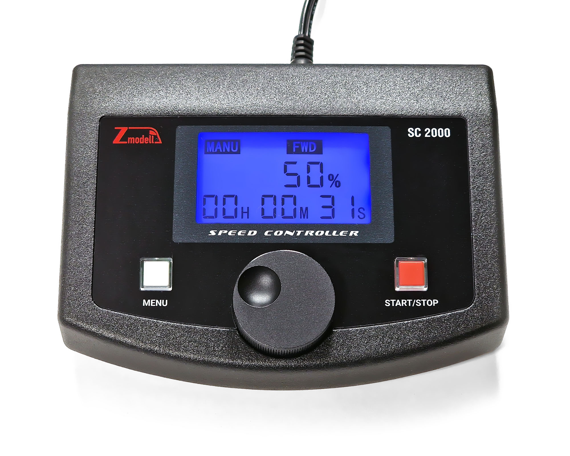
This is how the controller looks in driving mode:
LED backlight can be turned off and on by the long press of “MENU” button:

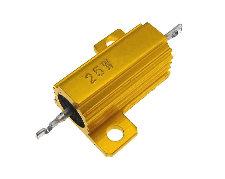
In order to improve driving characteristics of locomotives equipped with small coreless motors, it is recommended to remove all capacitors in the track circuit - just like in digital mode. Alternatively, it is possible to achieve the similar effect by connecting shunting resistor in parallel to the track. For track voltage of 10 Volts the value should be 100 Ω, for higher voltages – 150-500 Ω, depending on the track voltage.
In order to avoid generating excessive heat, I recommend using powerful resistors (rated for 25W and higher), such as this model for example:
However, it should be noted that the total energy efficiency will be reduced in case of connecting shunting resistor. Around 100 mA of useful current will be dissipated as heat.
All these measures may be not necessary for bigger scales like N and H0, where even coreless motors draw higher currents, and therefore more "sensible" to the controller. I tested this PWM controller with H0 layout – all locomotives drove perfectly without removing any capacitors.
It is still possible to place orders at companies in Ukraine where I planned to produce parts for this device, but it is obviously more difficult now. I hope I will manage the manufacturing process in the future to be able to produce this controller in bigger quantities.
Best regards,
Alex
I would like to reveal one more development that I started back in Ukraine, but managed to finish only recently due to the lack of time and complexity of the project. It is a second generation of the digital programmable PWM speed controller Zmodell SC-1000 I presented 3 years ago: azlforum.com/thread/1698/zmodell-digital-programmable-speed-controller. Along with more sophisticated design, the new construction features a number of major updates and new features and received a designation SC-2000:
Like the first version, the new model is capable of controlling any kinds of locomotives of all scales from Z to G equipped with both conventional DC brushed motors as well as with coreless motors.
List of features
- Input voltage – 10-50 Volts (output voltage equals to input voltage)
- Two outputs – DC and PWM controlled
- Total output current – 5A
- PWM control frequency – 15 kHz
- Two control modes – manual and automatic
- Adjustable slow start and stop feature for both modes
- Programmable functions: forward time, stop time, reverse time
- Support of 2 stop sensors for forward and reverse direction
- Overcurrent and thermal protection
- LCD screen with switchable backlight
- Remote control
- Size: 142 x 112 x 55 mm
Package list
- SC-2000 PWM Speed Controller
- Power supply (10V/3A for Z scale variant)
- Remote control
- 2x 1.5 m extender cables
- 2x 1.5 m sensor cables
- 2x male power adapters
- 2x female power adapters
- 2x male sensor adapters
- 2x female sensor adapters
- 8x 0.5 m flexible wires (red and black)
Here is a visual comparison of the new SC-2000 controller with its predecessor, SC-1000:
Differences from previous model
New rotary control knob
I decided to change the way of controlling the driving speed and direction to more intuitive and ergonomic. Three push buttons “UP”, “DOWN” and “DIRECTION” were replaced with a single rotary knob combined with a push button. Actually, this became to me the first reason to develop a new version of device – to equip it with digital rotary controller widely used in different power supplies and digital command stations.
For this reason, I developed a special module that converts signals from the digital encoder to the two individual switching lines that can replace “UP” and “DOWN” buttons. Used digital encoder is also combined with a push button that replaces “DRIVING DIRECTION” in my case. Digital encoder is a mechanical device similar to analog potentiometers that produces two series of switching impulses shifted with each other by a half-length of a single impulse):
New rotary knob allows not only to control the speed and direction of the train, but also adjusting settings in device’s menu. It is made of high-quality black anodized aluminum.
Remote control
PWM module used in my device supports remote control via radio channel. This way of wireless connection has an obvious advantage: user does not have to care about direct visibility between the remote control and the main device and can focus solely on controlling the train, regardless of the position in the room.
So far, I decided to use existing model of remote control that is suitable to my PWM controller. I plan to develop my own remote control in the future – more advanced, and also featuring very convenient and ergonomic rotary knob instead of buttons. Current model of remote control is powered by a single CR2032 battery.
Support of starting and ending points
PWM controller offers one more new feature – support of forward and reverse stop points with a help of sensors. Any kind of normally open mechanical switch, optocoupler switch, Hall sensor or reed switch can be used for this purpose.
With this new feature, it is very easy to set up a shuttle operation between two stations on the layout. Furthermore, it can be now set up in two different ways: using preprogrammed values (setting time and speed for forward, stop and reverse) and also with a help of sensors. For example, the train departs from the first station, reaches the sensor at the second station and stops there, waits for a predefined period of time and then starts driving in reverse direction until it reaches the sensor at the first station and stops there once again.
Controller offers 4 different modes:
1. No stop points. Sensors are not used.
2. The train starts forwards, reaches forward sensor and stops there.
3. The train starts forwards, reaches forward sensor and stops there. Then it starts in reverse direction, reaches reverse sensor and stops there.
4. Loop operation: The train starts forwards, reaches forward sensor and stops there. Then it starts in reverse direction, reaches reverse sensor and stops there. After this, the cycle repeats again until the stop button is pressed.
Here is what’s inside the device:
Functions of controls:
- “MENU” – Enters settings and programming menu. Continuous pressing of this button scrolls the list of available settings and programmable functions. Long press switches LED backlight on and off.
- Central rotary knob with push button – Driving mode: adjusts train speed. Pressing the button changes driving direction in manual mode. Programming mode: adjusts settings.
- “START/STOP” – Driving mode: Starts/stops the train in manual mode or starts/stops the pre-programmed sequence in automatic mode. In manual mode, last used direction of travel is remembered. Programming mode: exits menu and returns to driving screen.
Modes and settings
Device works in three modes – Manual, Auto and Programming. In manual mode, “MANU” sign and speed (in %) indicated on the screen. Also, current direction of travel (“FWD”/”REV”) and total running time is shown.
In Auto mode, “AUTO” sign, speed and current direction of travel (“FWD”/”REV”) are indicated. Countdown timer in the numeric section shows remaining time of the current operation (forward, reverse driving or pause).
Pressing “MENU” button enters settings and programming menu. Continuous pressing of this button scrolls the list of available settings and programmable functions. Here is a list of them:
- Function 0: 1 is manual mode, 2 is automatic mode. The default is 1 manual mode.
- Function 1: Acceleration time. Range: 0-10 seconds (values 000-100; pitch is 0.1 second). The default is 1 second (value 10).
- Function 2: Deceleration time. Range: 0-10 seconds (values 000-100; pitch is 0.1 second). The default is 1 second (value 10).
- Function 3: Starting speed. Range: 000-080. The minimum speed is adjustable between 0-80% and less than the maximum speed setting. The default is 0.
- Function 4: Maximum speed. Range: 000-100. The maximum speed is adjustable between 0-100% and is higher than the minimum speed setting. The default is 100.
- Function 5: Acceleration and deceleration steps setting (for manual mode). Values: 001, 002, 005, 010, 015, 020, 025. Each click of the rotary knob changes the speed by 1%, 2%, 5%, 10%, 15%, 20% and 25%.
- Function 6: Total running time. Range: 1 second – 99 hours 59 minutes 59 seconds. The default is 99 hours 59 minutes 59 seconds.
- Function 7: Forward running time (for automatic mode; acceleration time is not included). Range: 1 second – 99 hours. Default is 10 seconds.
- Function 8: Stop time (for automatic mode). Range: 1 second – 99 hours. Default is 10 seconds.
- Function 9: Reverse running time (for automatic mode; acceleration time is not included). Range: 1 second – 99 hours. Default is 10 seconds.
- Function E: Using sensors. Range: 1-4.
1. No stop points. Sensors are not used.
2. The train starts forwards, reaches forward sensor and stops there.
3. The train starts forwards, reaches forward sensor and stops there. Then it starts in reverse direction, reaches reverse sensor and stops there.
4. Loop operation: The train starts forwards, reaches forward sensor and stops there. Then it starts in reverse direction, reaches reverse sensor and stops there. After this, the cycle repeats again until the stop button is pressed.
Note: Automatic mode is possible only when the stop sensors are not used (function E set to 1). Forward and reverse speed can be set independently while driving for both automatic and manual modes.
Design of the housing is my own. The case is printed on Hewlett-Packard Multi Jet Fusion 3D printer using PA12 material – very strong and durable material that is suitable for use in functional parts. It has a grainy surface that suits very well for housings of various devices. The case then was painted in black and varnished. The company where I printed this case (and also other similar kinds of products) is located in Odessa, Ukraine.
Glossy front panel is milled out from 1 mm acrylic plastic on a CNC machine, and then printed from the bottom side on Mimaki UV-printer.
The output circuit is based on powerful MOSFETs with ultra-low heat dissipation. Thermal safety is provided by resettable fuses that protect both outputs – DC and PWM controlled. For Z scale, I installed 500 mA fuses. Models with higher current can be used in variants for bigger scales.
Functioning principle of this type of fuses is easy. In normal state, resistance of the fuse is around 0.5-0.6 Ohms. When the current exceeds rated value, the fuse starts to heat up and to increase its resistance quickly. As a result, the current also quickly drops down. After this, some time is needed for the fuse to recover.
Rear panel:
From the left to the right: power switch, power input, DC output, PWM output, forward stop sensor, reverse stop sensor. DC output is a pass-through that can be switched off by the power switch. This output is used to control accessories – turnouts, servos, relays, signals, lighting etc. PWM output is connected to the track.
5.5 x 2.5 mm connectors are used for power input, DC and PWM outputs. Stop sensors are connected by cables with 2-pole 3.5 mm mini-jack plugs. I included in the package a set of adapters which allow to connect the wires either to the main unit directly or with additional extender cables.
This is how the controller looks in driving mode:
LED backlight can be turned off and on by the long press of “MENU” button:
In order to improve driving characteristics of locomotives equipped with small coreless motors, it is recommended to remove all capacitors in the track circuit - just like in digital mode. Alternatively, it is possible to achieve the similar effect by connecting shunting resistor in parallel to the track. For track voltage of 10 Volts the value should be 100 Ω, for higher voltages – 150-500 Ω, depending on the track voltage.
In order to avoid generating excessive heat, I recommend using powerful resistors (rated for 25W and higher), such as this model for example:
However, it should be noted that the total energy efficiency will be reduced in case of connecting shunting resistor. Around 100 mA of useful current will be dissipated as heat.
All these measures may be not necessary for bigger scales like N and H0, where even coreless motors draw higher currents, and therefore more "sensible" to the controller. I tested this PWM controller with H0 layout – all locomotives drove perfectly without removing any capacitors.
It is still possible to place orders at companies in Ukraine where I planned to produce parts for this device, but it is obviously more difficult now. I hope I will manage the manufacturing process in the future to be able to produce this controller in bigger quantities.
Best regards,
Alex


