|
|
Post by scanrail on Oct 30, 2019 15:22:29 GMT -5
Hi friends, After a number of requests I decided to create a thread about my buffer circuit boards I have recently developed. There are 3 different PCB's available. Type A is based on 470 μF 16V or 220 μF 16V Tantalum capacitors. Types B and C are based on 100 μF 16V X7R ceramic SMD 1206 capacitors. Circuit boards are designed in a such way that they can be cut off to many different sizes. Various thickness is also available if capacitors populated on a single or both sides of PCB. Type A is not suitable for analog mode since it is based on polarity-sensitive capacitors. Only B and C types are suitable for analog (without a diode and with a resistor with lower value). Buffer circuits are based on the 'classic' scheme with 100 Ohm resistor and diode. Type A is equipped with a 15V Zener diode for additional safety with Tantalum capacitors. Types B and C don't feature a Zener diode because ceramic capacitors are much less sensitive to a possible overvoltage scenarios. Also I did not included it in order to save more space on a very small PCB. Buffer boards can be useful for both digital and analog locomotives. All boards were successfully tested and already used in a number of my own projects, as well as other projects. Links below lead to the German forum: Märklin 88761 Rail Zeppelin digital: f.z-freunde-international.de/viewtopic.php?f=16&t=13411Märklin 88830 BR52 steam locomotive digital with sound: f.z-freunde-international.de/viewtopic.php?f=16&t=13563Sound decoder for BR38: f.z-freunde-international.de/viewtopic.php?f=16&t=14033Please take a look at the picture for detailed specifications. Red vertical lines show how each PCB can be cut: 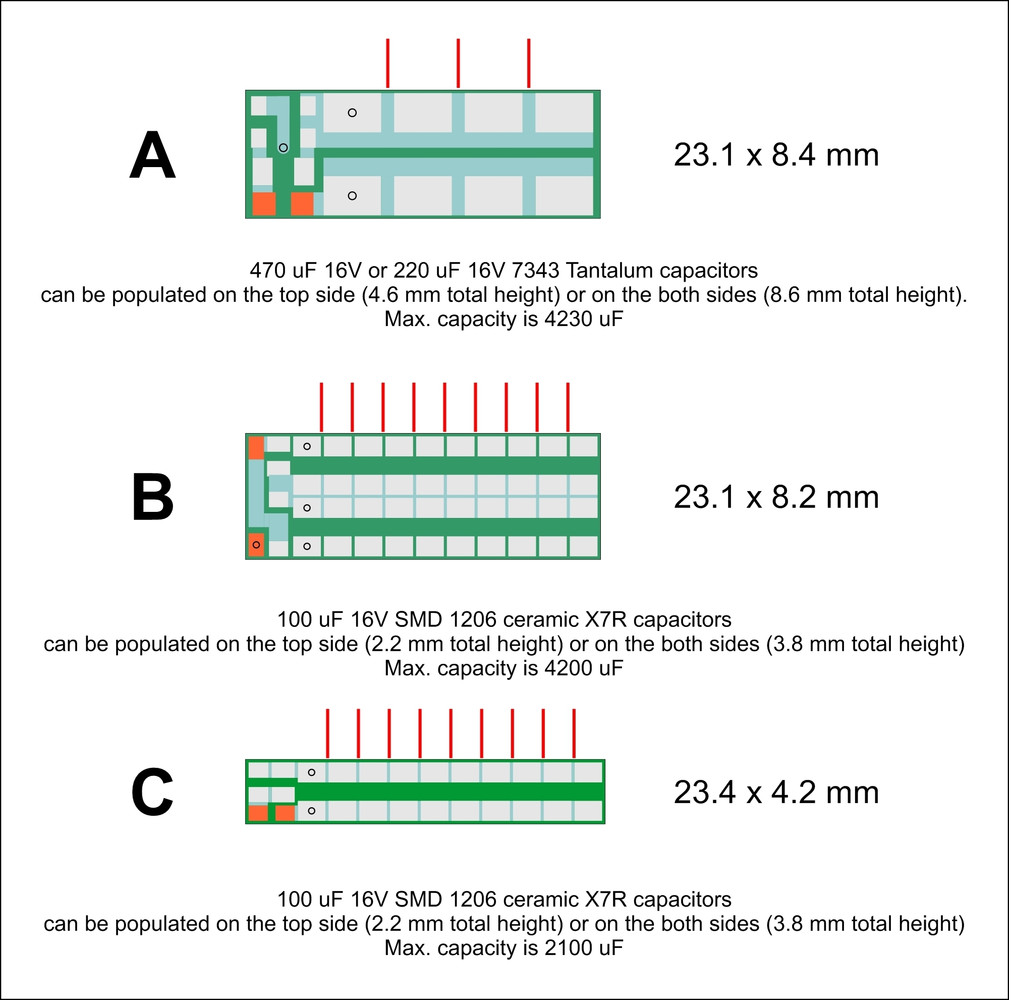    The sizes are given above without a shrinking tube. Buffer boards will be slightly bigger with it. Anyone interested please let me know. Regards, Alex |
|
Deleted
Deleted Member
Posts: 0
|
Post by Deleted on Oct 30, 2019 16:14:15 GMT -5
I can see why You wanna embed filtering capacitors, in order to avoid "flicker" with digital circuits, which could lead to malfunction (at least it's what I understood). But, why for ANALOG (traditional) locomotives ? Do You hope such capacitors hold enough power to allow the engine to run over bad contact places ? Or, what is the purpose of such a circuit for "simple" locomotives ?
And, sorry, the forum You are mentioning denies any access to non-members ...
|
|
|
|
Post by scanrail on Oct 30, 2019 18:02:22 GMT -5
Hi Alberich,
Bad contact between wheels and tracks, jerks and stalls - all this is very common to any railway model scales, and the smaller the scale, the more it is pronounced. There is usually very little space in any Z scale locomotive to accommodate almost any kind of buffering, so it is a situation where anything is better than nothing. Buffering effect will be more visible on locomotives equipped with coreless motors that consume very low current. Surely it would be hard to buffer old 'voracious' motors (like used in MTL F7's for example), but even here 2000 μF will be helpful. Such keep-alive capacitors are often called 'electronic flywheels'.
|
|
|
|
Post by markm on Oct 30, 2019 18:43:37 GMT -5
Actually probably the best English term is stay-alive circuit.
Mark
|
|
|
|
Post by husafreak on Nov 2, 2019 0:28:27 GMT -5
Oh I loved the term "electronic flywheel" !
|
|
|
|
Post by husafreak on Nov 2, 2019 0:30:39 GMT -5
And I like the idea of trying one of these in a DC loco.
|
|
|
|
Post by tjdreams on Nov 2, 2019 10:58:12 GMT -5
Alex Most of us can not read German so the links to the German forum don't help. Can you translate and post the info you wanted us to see to english and post it here?
I am interested but i do have a few questions first
What's the price for the boards? and the components?
Have you tried to install this into any American style Loco's? If so do you have a list of which models that it fits in?
How bout a wiring diagram or instructions on how its wired into a analog and a DCC Loco?
David
|
|
|
|
Post by scanrail on Nov 2, 2019 22:18:55 GMT -5
Hello David, It's a pity that these threads from German forum are not visible to unregistered users, unfortunately I can do nothing with this. And I read German very little too and chat on mentioned forum using on-the-fly translation to English in Google Chrome. However, I post there a lot of info in English. First two links lead to my own threads about using these buffer PCB's in combination with DCC decoders. In a couple of words, the effect is excellent and very pronounced, and many decoders work totally differently when buffered this way. I don't think it makes a big sense to copy all these long-reads here, so I post just a few pictures: Using type B buffer in Rail Zeppelin (Marklin 88761) in combination with DCC decoder CT Elektronik DCX77z: 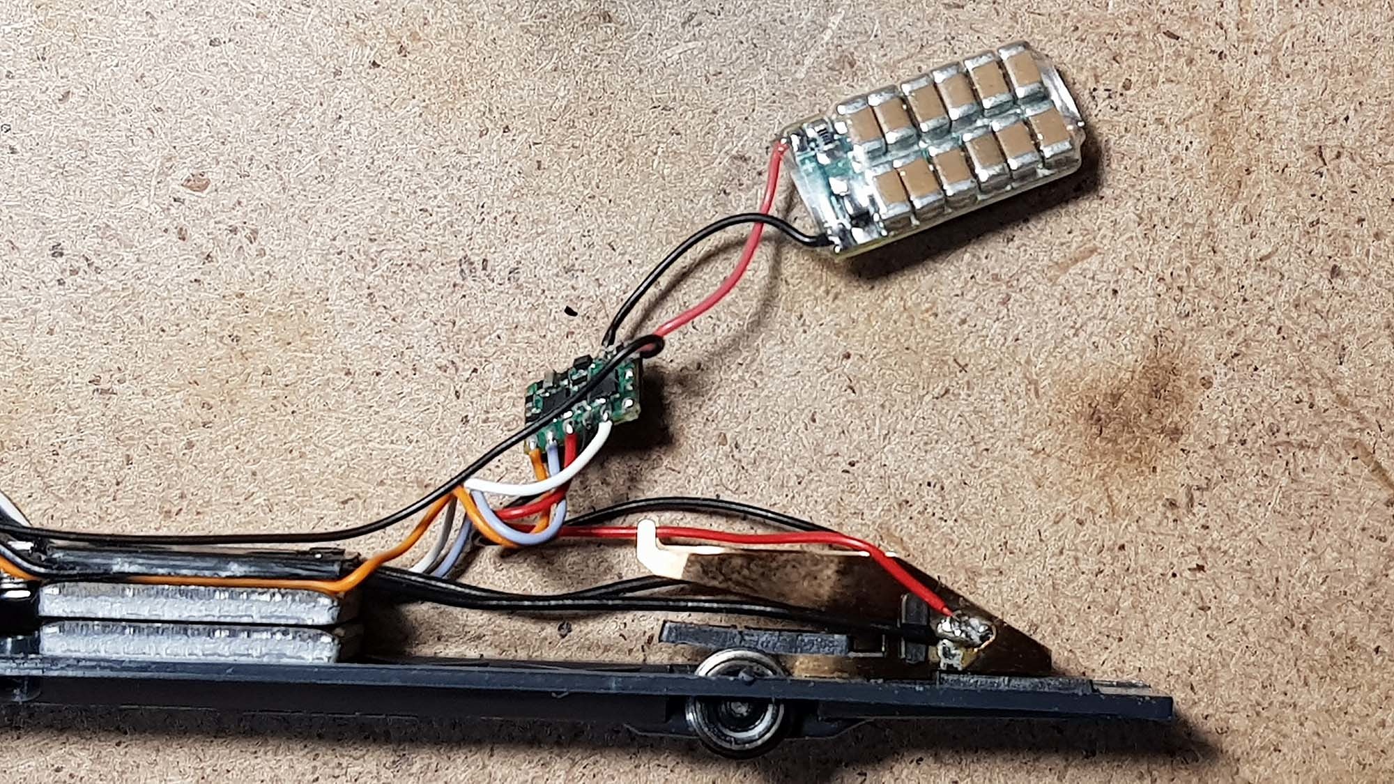 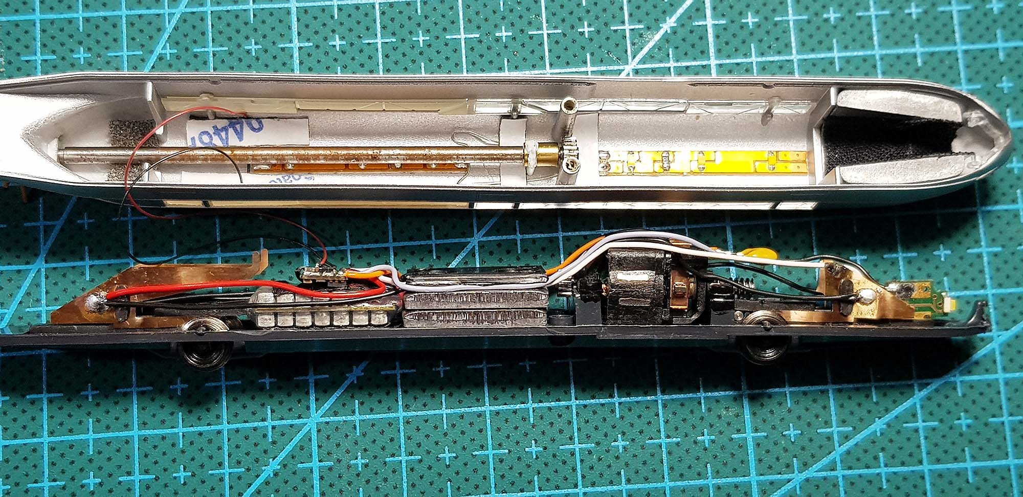 Using type C buffer in German Class 52 steam locomotive (Marklin 88830) in combination with multiprotocol sound decoder Doehler & Haass SD10A: 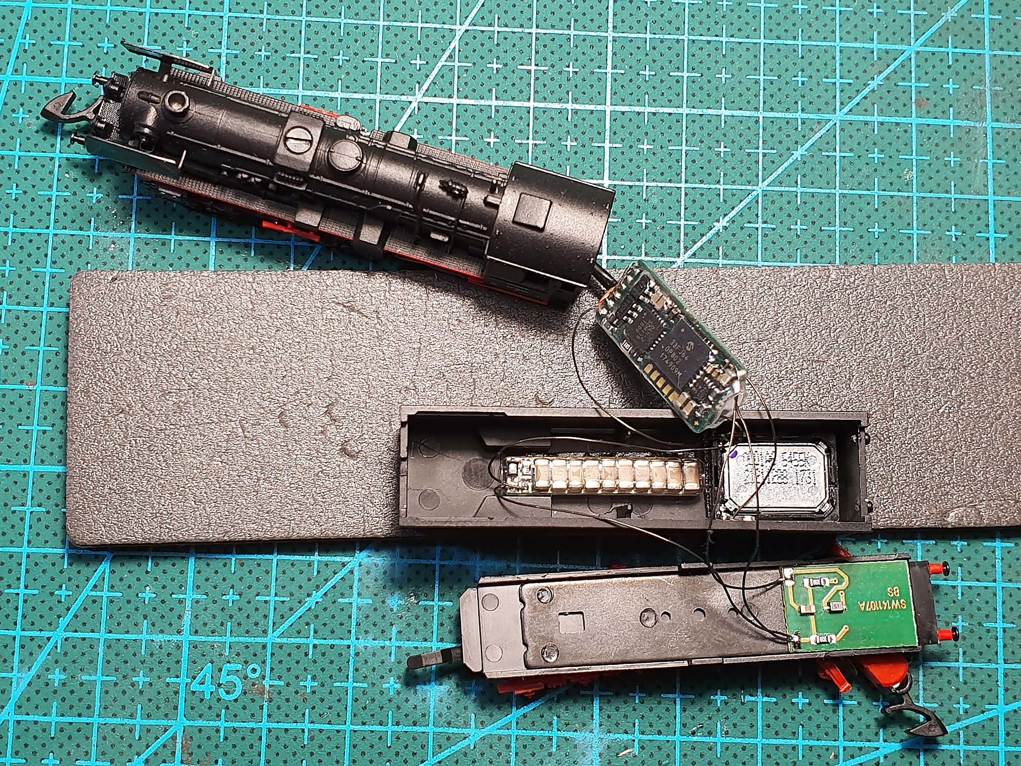 Using type C buffer in German 3-axle baggage car in combination with multiprotocol sound decoder Doehler & Haass SD18A: 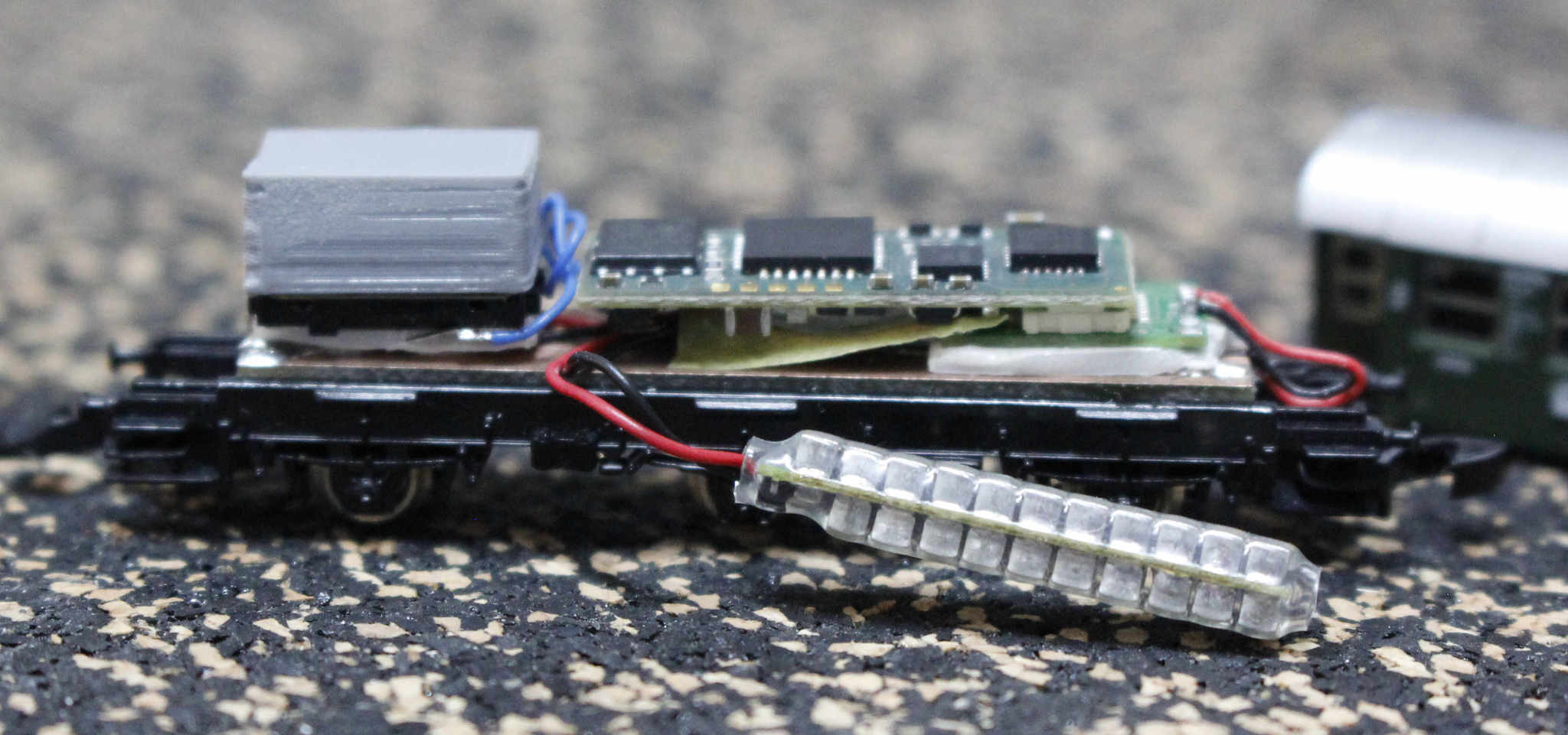 About pricing: I would like to offer these boards already assembled and carefully tested. Price is $15 per board (any type). About compatibility: I did not designed these boards keeping in mind a particular model of locomotive; the main goal was to make them as small as possible, and provide a highest possible capacity in a given volume. For this purpose I found very small 100 μF 16V SMD 1206 X7R ceramic capacitors. These capacitors have a number of important advantages: they are not polarity sensitive, that allows using them for buffering DC analog locos, and they have a much higher capacitance density that cannot be offered by any kind of classic can-type electrolytic capacitors. My US locomotive fleet consists of various AZL diesels, AZL Mikado, a number of MTL F7's and MTL SD40-2. There is also a number of Marklin version of E8/E9 diesels and Marklin F7's. All my AZL diesels (and Marklin E8/E9) equipped with Digitrax DZ123Z0 decoders (MTL SD40-2 with DZ123M0), I like very much how they work even on slightly dirty tracks, and I didn't make any tests with such buffers. Furthermore, in most cases there is no room for additional enhancements inside most AZL locos, so I can hardly imagine if someone will manage to add such buffer PCB there. Additionally, there is no info on how buffer capacitors can be attached to Digitrax drop-in decoders (maybe it is possible, however I didn't explored this question yet). Digitrax offers "Power-Xtenders": www.digitrax.com/products/power-xtenders/, but they intended to use with their other kinds of decoders. My Mikado is equipped with Doehler & Haass DH05C decoder. This decoder is buffer-capable. However again, there is no room inside Mikado's tender to add anything except decoder itself. Marklin F7's are digitized with drop-in decoders LDS26306-U from German manufacturer Velmo. These decoders are also based on Doehler & Haass DH05C chips. It is hard to attach a buffer PCB to them due to a fact that they are dedicated to a particular model of locomotive. About functioning principles and connecting buffer capacitors to decoders: I would like to give a link to a very detailed article on German site (I'm sorry, it's again in German  , please use Google Chrome translate): www.1001-digital.de/pages/basteln-bauen/elektronisches/anleitungen/pufferschaltung-fuer-16-v-smd-kondensatoren.phpMy boards are built exactly using the circuit diagram described there (with one exception: I excluded Zener diodes from variants B and C). In DC analog mode these buffer boards are simply attached in parallel with motor. That's all. However, in order to use with DC analog type B and C boards should be slightly modified - I have to remove a diode and reduce resistor value to about 1-10 Ohms (again, it is a reason why I would like to sell them already assembled). Type A board is not suitable for DC analog since it is based on polarity sensitive Tantalum capacitors. Regards, Alex |
|
|
|
Post by tjdreams on Nov 3, 2019 11:10:46 GMT -5
Alex
This explains a lot. You've got my interest. I have several DC loco's that could use just this kind of boost. I need to pull a couple of them out and measure to see which will fit best B or C and single or double sided. You can expect a order from me in a couple weeks. Right now I'm busy trying to get ready for another show next weekend.
Thanks
David
|
|
|
|
Post by scanrail on Nov 3, 2019 16:51:25 GMT -5
Hi David,
Thanks! No need to hurry, because after a number of orders from Germany I ran out of empty circuit boards, so I have to order them again from my local manufacturer (I will do this in any case).
Regards,
Alex
|
|
|
|
Post by BAZman on Nov 3, 2019 17:21:33 GMT -5
Alex, good work. Working across the street from an electronics surplus store lead me to a few reels of the caps. I made mine out of "Perf Board" (blank boards with copper pads at each o.1 grid. Amazon and such. But, you have to do all the wiring between the holes so it makes it 'bigger' that it needs to be.
Your solution is ideal, perfect. choose a B or C primary size and trim the length, if needed. I would like a 'starter' board option the Protection diode(s) and resistor, for making short 2 or 4 cap types for passenger lighting or such. Maybe the same for the 'A' DCC board where space may be limited. Crazy to have to cut off 14 caps !
$15 is a good price. Let us know how to purchase (PayPal 'Friends' is free for us)
|
|
|
|
Post by scanrail on Nov 3, 2019 18:23:43 GMT -5
Hi Jeff,
Yes, I know these prototype boards. They are also usually too thick for this purpose (1-1.5mm). My boards are only 0.5mm thick, so it allows to save even a bit more space. For using in digital mode each type of board always includes a diode and resistor, however only type A has a Zener diode, since Taltalum electrolytic capacitors are sensitive to overvoltage.
I decided to exclude Zener diode from B and C types in order to save even more space, that is critical in many applications. Ceramic capacitors are very resistant to overvoltage - numerous tests show that many ceramics with 16 V nominal voltage easily withstand up to 30 V without any damage. Even in the worst scenario they will never explode and burn out (unlike Tantalum ones).
Considering that a recommended voltage for Z scale is around 8-10 V (12 max.), it is 100% safe to use these ceramic capacitors without a voltage stabilizing Zener diode, especially in such limited space applications.
As I already wrote, in order to use B and C boards in DC analog mode (type A is only suitable for digital), I have to remove a diode to let the buffer work in both driving directions. Resistor value should be also lowered down to 1-10 Ohms in order to protect a power controller and/or to prevent false triggering of the short circuit protection if controller has any. (In general, resistor can be removed completely if the total buffer capacity is low - say, about 500 μF).
About payments: Surely, I accept PayPal.
About shipping: Usually it takes about 2-4 weeks from Ukraine to USA. I still have to check shipping rates, however don't worry, they are very fair.
Regards,
Alex
|
|
|
|
Post by Commodore on Nov 7, 2019 8:43:06 GMT -5
Thanks Alex!
I am very aware of electrical contact problems in Z scale.
I am also very appreciative of your efforts to solve these.
Your add-on weights make a huge difference in the running of the Marklin GG1. Thank you!
You are on to something important with your buffer boards. They have potential to vault z-scale ahead of N-scale. N-scale suffers from the same lack of realistic running expectations but with much less spatial grace. Physically, Z-scale is simply "way more" esthetically pleasing.
You are doing the lord's work😬
Thank you, again!
|
|
|
|
Post by zscalehobo on Nov 7, 2019 22:05:04 GMT -5
(PayPal 'Friends' is free for us) Not anymore. It's a modest fee for the sender when paying a non-US recipient. |
|


 , please use Google Chrome translate):

